EN - 21
Engl
ish
Deutsch
F
rançais
Operating the Tractor
Installing the Mower Deck
Note:
Perform mower installation on a hard, level sur-
face such as a concrete floor.
1. Park the tractor, disengage the PTO lever, turn off the
engine, remove the key, disconnect the spark plug
wire(s), and engage the parking brake.
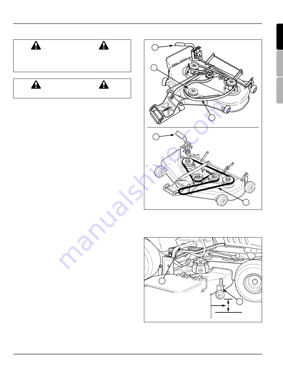
2. Place mower in the lowest cutting position using the
cutting height adjustment lever (A, Figure 7).
3. Turn the wheels left, and slide the mower deck under
the tractor.
4. Turn the wheels straight ahead and align the rear
mounting brackets (D, Figure 5).
5. Pull the spring-loaded lever (B, Figure 6) forward,
hook the mower hitch on the tractor bracket (A).
Release the spring loaded lever to lock the mower
hitch in the tractor bracket.
6. Install the long hitch pin (A, Figure 5) through the rear
mounting brackets. Secure with a hair pin clip.
Note:
If the rear mounting bracket holes are not aligned,
shift the mower deck and turn the front wheels slightly.
7. Install the mower drive belt (B, Figures 7) on the
engine pulley; flex the engine belt guide rearward
slightly to get the belt onto the pulley.
8. Connect the clutch rod (C, Figure 4) to the bottom of
the PTO lever (B). Secure using a hair pin clip.
9. Check the PTO adjustment (see PTO Clutch
Adjustment in the Adjustment Section).
MOWER CUTTING HEIGHT ADJUSTMENT
1. Pull the cutting height adjustment lever (B, Figure 8)
back and to the left to release it.
2. Set the mower cutting height to the desired level.
3. Move the lever to the right to lock it.
4. Remove the pin & clip ( A, Figure 8) from each
mower deck front gauge wheel.
5. Adjust the gauge wheels to achieve the appropriate
mower deck-to-ground clearance, as shown in
Figure 8. Reinstall pin & clip to each wheel.
Engage parking brake, disengage PTO, stop engine,
disconnect spark plug wire(s), and remove key before
attempting to install or remove the mower.
WARNING
The muffler and surrounding areas may be hot.
CAUTION
Figure 7. Mower Belt Routing
A. Mower Height Adjustment Lever
C. Engine Pulley
B. Mower Drive Belt
Figure 8. Mower Deck - Right Side
A. Pin and Clip
B. Height Adjustment Lever
20-25 mm with Height
Adjustment lever in
lower
3
cutting positions
50 mm with Height Adjustment
lever in
upper
3 cutting positions
A
B
B
B
C
A
A
Mower Deck 38”
Mower Deck 44”
Summary of Contents for MT 830
Page 2: ...THIS PAGE INTENTIONALLY BLANK...
Page 4: ...R 1720558 06 2001 VIKING Umwelttechnik A 6330 Kufstein...
Page 6: ......
Page 14: ...Assembly EN 8 1 2 C D FITTING THE WHEELS Rear wheels A B...
Page 60: ...DE 8 Zusammenbau 1 2 C D ANBAU DER R DER Hinterr der A B...
Page 106: ...FR 8 Assemblage 1 2 C D MONTAGE DES ROUES Roues arri re A B...


