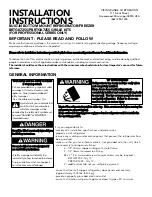
INSTALLATION
INSTRUCTIONS
BUILT-IN BOTTOM MOUNT REFRIGERATOR/FREEZER
BRTGK72SS/PBRTGK72SS GRILLE KITS
(FOR PROFESSIONAL SERIES ONLY)
VIKING RANGE CORPORATION
111 Front Street
Greenwood, Mississippi 38930 USA
(662) 455-1200
IMPORTANT - PLEASE READ AND FOLLOW
Make sure that incoming voltage is the same as unit rating. An electric rating plate specifying voltage, frequency, wattage,
amperage, and phase is attached to the product.
P
Plle
eaasse
e rre
effe
err tto
o IIn
nssttaallllaattiio
on
n IIn
nssttrru
uccttiio
on
nss p
prro
ovviid
de
ed
d w
wiitth
h b
bo
otttto
om
m m
mo
ou
un
ntt rre
effrriig
ge
erraatto
orr//ffrre
ee
ezze
err ffo
orr aad
dd
diittiio
on
naall iin
nffo
orrm
maattiio
on
n..
To reduce the risk of fire, electric shock, or injury to persons, installation work and electrical wiring must be done by qualified
people in accordance with all applicable codes and standards, including fire-rated construction.
The installer should leave these instructions with the consumer who should retain for local inspector’s use and for future
reference.
GENERAL INFORMATION
It is your responsibility to :
-comply with installation specifications and dimensions
-properly install refrigerator
-remove any moldings or decorative panels that prevent the refrigerator from
being serviced
-make sure that you have these materials, (not provided with the unit), which
are necessary for proper installation:
2 - 1/4” (6 mm) copper tubing with shutoff valve
2 - 1/4” (6mm) compression fitting
#8 x 3” (7.6 cm) wood screws (Longer screws may be required.)
BRTGK72SS - Qty 12
PBRTGK72SS - Qty 12
2 - saddle valves (do not use self-piercing valves).
-assure that floor will support refrigerator, door panels and contents,
(approximately 1200 lbs. [540 kg.])
-provide a properly grounded electrical outlet
-assure that location will permit appliance doors to open 90
o
minimum
M
Mo
osstt o
off tth
he
e rre
effrriig
ge
erraatto
orr’’ss w
we
eiig
gh
htt iiss aatt tth
he
e tto
op
p.. E
Exxttrraa ccaarre
e iiss n
ne
ee
ed
de
ed
d w
wh
he
en
n m
mo
ovviin
ng
g tth
he
e
rre
effrriig
ge
erraatto
orr tto
o p
prre
evve
en
ntt ttiip
pp
piin
ng
g..
K
Ke
ee
ep
p ccaarrd
db
bo
oaarrd
d ssh
hiip
pp
piin
ng
g p
piie
ecce
e o
orr p
pllyyw
wo
oo
od
d u
un
nd
de
err rre
effrriig
ge
erraatto
orr u
un
nttiill iitt iiss iin
nssttaalllle
ed
d iin
n
tth
he
e o
op
pe
erraattiin
ng
g p
po
ossiittiio
on
n..
Y
Yo
ou
urr ssaaffe
ettyy aan
nd
d tth
he
e ssaaffe
ettyy o
off o
otth
he
errss
iiss vve
erryy iim
mp
po
orrttaan
ntt..
We have provided many important safety
messages in this manual and on your
appliance. Always read and obey all
safety messages.
This is the safety alert symbol. This
symbol alerts you to hazards that
can kill or hurt you and others.
All safety messages will be
preceded by the safety alert symbol and
the word “DANGER” or “WARNING”.
These words mean:
Y
Yo
ou
u w
wiillll b
be
e kkiilllle
ed
d o
orr sse
erriio
ou
ussllyy iin
njju
urre
ed
d iiff yyo
ou
u
d
do
on
n’’tt ffo
ollllo
ow
w iin
nssttrru
uccttiio
on
nss..
Y
Yo
ou
u ccaan
n b
be
e kkiilllle
ed
d o
orr sse
erriio
ou
ussllyy iin
njju
urre
ed
d iiff
yyo
ou
u d
do
on
n’’tt ffo
ollllo
ow
w iin
nssttrru
uccttiio
on
nss..
All safety messages will identify the
hazard, tell you how to reduce the chance
if injury, and tell you what can happen if
the instructions are not followed.
T
TIIP
P O
OV
VE
ER
R H
HA
AZ
ZA
AR
RD
D
R
Re
effrriig
ge
erraatto
orr iiss tto
op
p h
he
eaavvyy aan
nd
d ttiip
pss e
eaassiillyy w
wh
he
en
n
n
no
ott cco
om
mp
plle
ette
ellyy iin
nssttaalllle
ed
d..
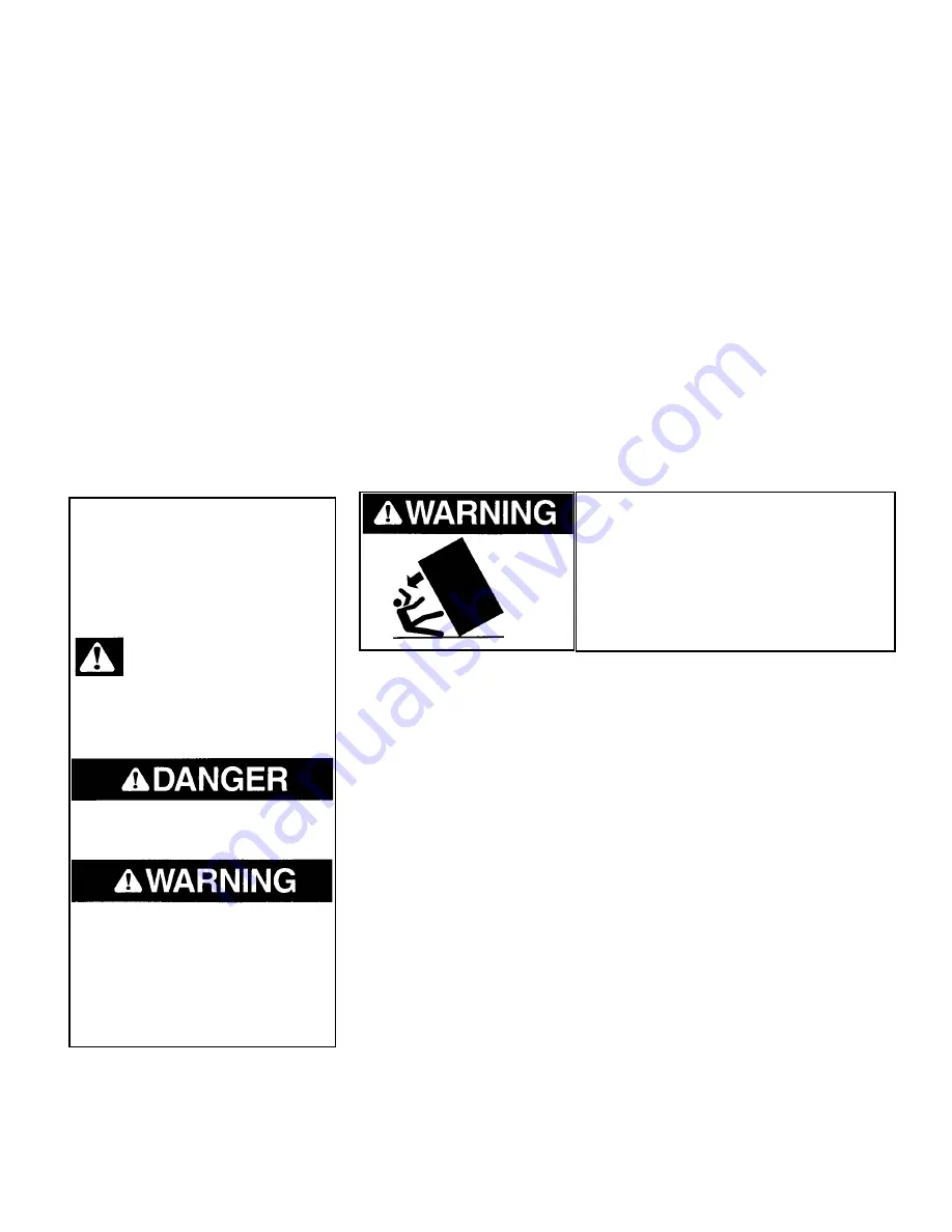
K
Ke
ee
ep
p d
do
oo
orrss ccllo
osse
ed
d u
un
nttiill rre
effrriig
ge
erraatto
orr iiss
cco
om
mp
plle
ette
ellyy iin
nssttaalllle
ed
d aan
nd
d sse
eccu
urre
ed
d w
wiitth
h llaag
g b
bo
ollttss
tto
o rre
eaarr w
waallll.. U
Usse
e ttw
wo
o o
orr m
mo
orre
e p
pe
eo
op
plle
e tto
o m
mo
ovve
e
aan
nd
d iin
nssttaallll rre
effrriig
ge
erraatto
orr.. F
Faaiillu
urre
e tto
o d
do
o sso
o ccaan
n
rre
essu
ulltt iin
n d
de
eaatth
h o
orr sse
erriio
ou
uss iin
njju
urryy

