background image

3

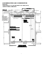
SITE PREPARATIONS AND CONSIDERATIONS

BRTGK72SS 
PROFESSIONAL 36” W. BOTTOM MOUNT DUAL INSTALLATION, 
CABINET OPENING DIMENSIONS

E

ELLE

EC

CT

TR

RIIC

CA

ALL

R

RE

EC

CE

EP

PT

TA

AC

CLLE

E

LLO

OC

CA

AT

TIIO

ON

NS

S

((S

SH

HA

AD

DE

ED

D  A

AR

RE

EA

AS

S))

1

1””  ((2

2..5

5  ccm

m))  T

TY

YP

P

F

FO

OU

UR

R  ((2

2  p

pe

err  u

un

niitt))

8

82

2  7

7//8

8””  ((2

21

10

0..5

5  ccm

m))  M

Miin

n..

aan

nttii--ttiip

p  b

bo

oaarrd

d  aan

nd

d  o

op

pe

en

niin

ng

g  h

he

eiig

gh

htt

8

84

4  1

1//1

16

6””  ((2

21

13

3..5

5  ccm

m))  M

Maaxx..

aan

nttii--ttiip

p  b

bo

oaarrd

d  aan

nd

d  o

op

pe

en

niin

ng

g  h

he

eiig

gh

htt

7

71

1  1

1//2

2””  ((1

18

81

1..6

6  ccm

m))  F

FO

OR

R  T

TW

WO

O  

P

PR

RO

OF

FE

ES

SS

SIIO

ON

NA

ALL  S

ST

TY

YLLE

E  3

36

6””  W

W..

B

BO

OT

TT

TO

OM

M  M

MO

OU

UN

NT

T  R

RE

EF

FR

RIIG

GE

ER

RA

AT

TO

OR

RS

S

3

35

5  1

13

3//1

16

6””  ((9

91

1..5

5  ccm

m))

3

39

9  3

3//1

16

6””  ((9

99

9..5

5  ccm

m))

W

Waatte

err  lliin

ne

e

e

en

nttrryy  aarre

eaa

W

Waatte

err

lliin

ne

e

W

Waatte

err

lliin

ne

e

Summary of Contents for Professional VCBB363

Page 1: ...wh he en n m mo ov vi in ng g t th he e r re ef fr ri ig ge er ra at to or r t to o p pr re ev ve en nt t t ti ip pp pi in ng g K Ke ee ep p c ca ar rd db bo oa ar rd d s sh hi ip pp pi in ng g p pi...

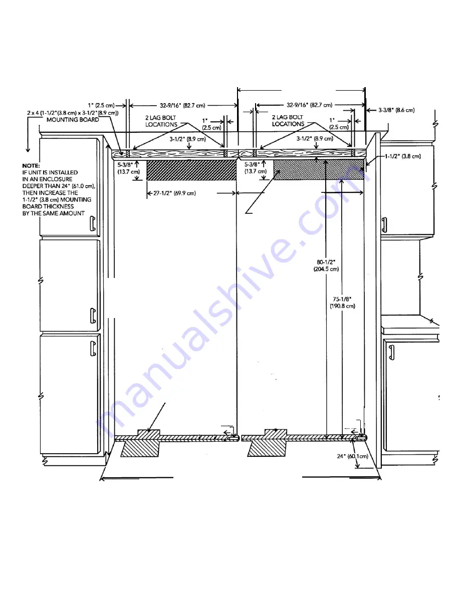
Page 2: ...69 2 cm Cutout Width 71 1 2 181 6 cm Cutout Height Min 82 7 8 210 3 cm Max 84 1 16 213 5 cm Cutout Depth 24 61 0 cm min Electrical Requirements 2 115 volt 60 Hz 15 amp dedicated circuit 3 wire cord w...

Page 3: ...bo oa ar rd d a an nd d o op pe en ni in ng g h he ei ig gh ht t 8 84 4 1 1 1 16 6 2 21 13 3 5 5 c cm m M Ma ax x a an nt ti i t ti ip p b bo oa ar rd d a an nd d o op pe en ni in ng g h he ei ig gh h...

Page 4: ...i ir rm ml ly y s se ea at te ed d u un nd de er r a an nt ti i t ti ip p b bo oa ar rd d 6 6 1 15 5 2 2 c cm m 6 6 1 15 5 2 2 c cm m 9 9 2 22 2 2 2 c cm m Electrical outlet location Electrical outlet...

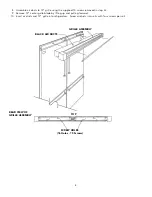
Page 5: ...re ef fr ri ig ge er ra at to or rs s 1 Position refrigerators in front of cutout 2 Remove the top air grille assemblies from both of the refrigerators a Remove the center grille blades by lifting up...

Page 6: ...ef ft t H Ha an nd d C Ca ab bi in ne et t S Si id de e T Tr ri im m P Po ow we er r S Sw wi it tc ch h S Sh ho ow wr ro oo om m S Sw wi it tc ch h 3 Verify operation by plugging in power cord Power...

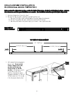
Page 7: ...t side trim that is mounted on the right hand side of the unit that is to be installed on the left side of the installation Replace this side trim with the connection J shaped side trim and shim inclu...

Page 8: ...ES 16 Holes 15 Screws 8 Assemble air ducts to 72 grille using the supplied 15 screws removed in step 2c 9 Remove 72 center grille blade by lifting up and pulling forward 10 Insert air ducts and 72 gri...

Page 9: ...n refrigerators in front of cutout 2 Remove the top air grille assemblies from both of the units a Remove full length center grille blade by lifting up and pulling forward b Remove the grille end cap...

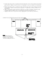
Page 10: ...r material should be located off the bottom of the unit and should not extend the entire height of the unit 7 Engage the right hand unit s left side trim into the J shaped portion of the left side uni...

Page 11: ...s to 72 grille using the 16 screws removed in step 2c 9 Remove 72 center grille blade by lifting up and pulling forward 10 Insert 72 grille into refrigerators Screw 72 grille assembly into units with...

Page 12: ...Viking Range Corporation 111 Front Street Greenwood Mississippi 38930 USA 662 455 1200 Specifications subject to change without notice http www vikingrange com F20083B PS0306VR...

Reviews: