background image

6

LLP

P//P

PR

RO

OP

PA

AN

NE

E  T

TA

AN

NK

K  C

CO

ON

NN

NE

EC

CT

TIIO

ON

N

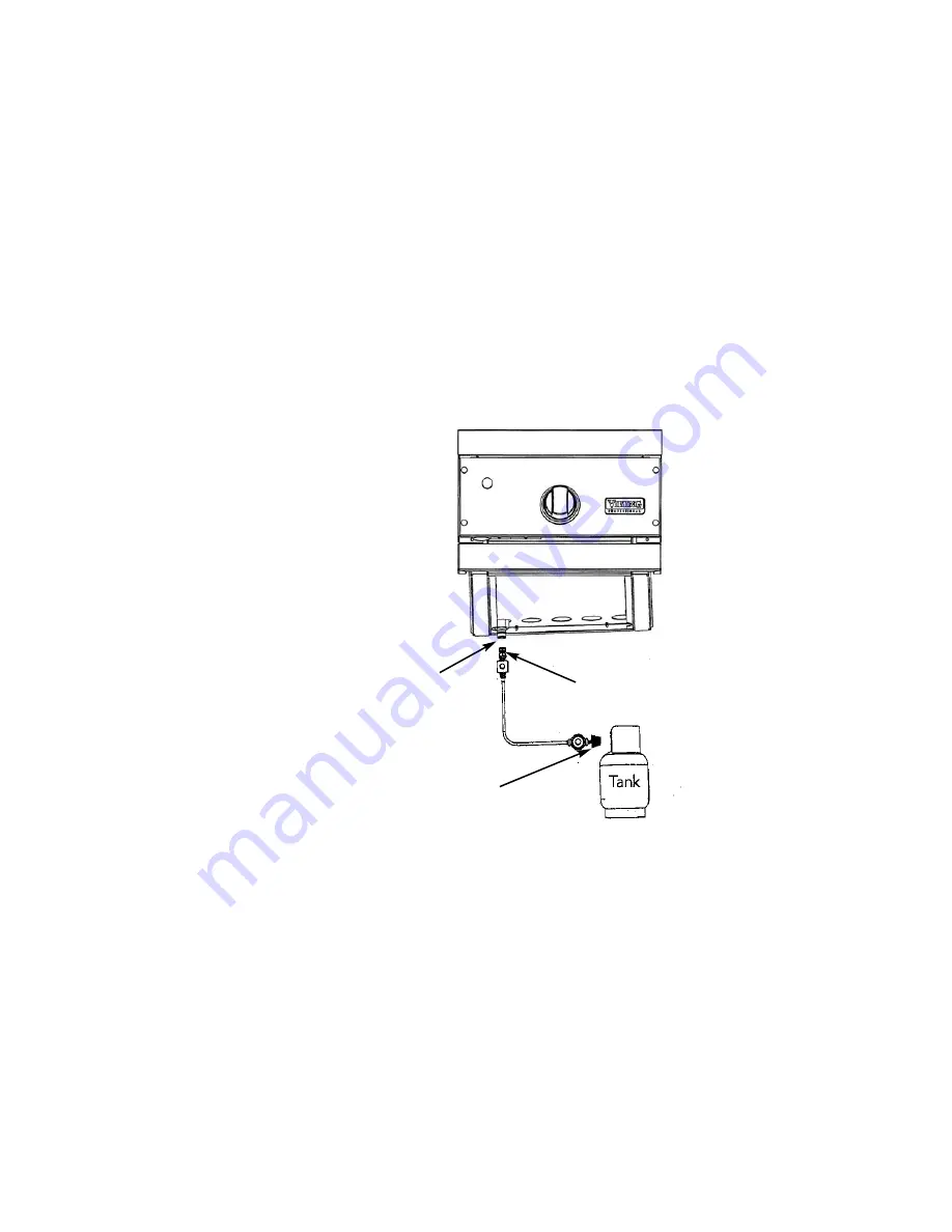
Outdoor side burners orificed for use with LP/Propane gas come equipped with a high capacity hose/regulator assembly
for connection to a standard 20 lb. LP/Propane cylinder e

eq

qu

uiip

pp

pe

ed

d  w

wiitth

h  aa  T

Tyyp

pe

e  1

1,,  Q

QC

CC

C--1

1  cco

on

nn

ne

ecctto

orr.. Hose assembly must

comply with 

Elastomeric Composite Hose and Couplings for Conducting Propane and Natural Gas, CAN/CGA-8.1 standard

or the 

Theromplastic Hose and Hose Couplings for Conducting Propane and Natural Gas CAN1-8.3 standard  (See

LP/Propane tank requirements below).  Each tank is supplied with a dust cap.  Place dust cap on cylinder valve outlet
whenever the cylinder is not in use.  Only install the type of dust cap on the cylinder valve outlet that is provided with the
cylinder valve.  Other types of caps or plugs may result in leakage of propane.

Connection:  1/2” (1.3 cm) NPT male with a 3/8” (.95) flare adapter
Operating Pressure:  10.0” W.C.P.

To connect to LP/Propane regulator/hose assembly:

Although the flow of gas is stopped when the connector is disconnected as part of its safety feature, you should
always turn the LP/Propane tank main valve “OFF” after each use and during transport of the tank or unit.  First
connect the regulator to the grill unit by screwing the 3/8” flare coupling to the 3/8” flare adapter.  Connect to the
tank valve by screwing the Type 1, QCC-1 connector to the LP/Propane tank.  Open the tank valve and check the
connection between the regulator and the Type 1, QCC-1 fitting for leaks with a soapy water solution.  If bubbles
appear, tighten the connection.  Repeat until all leaks have been stopped.  A

ALLW

WA

AY

YS

S  C

CH

HE

EC

CK

K  F

FO

OR

R  LLE

EA

AK

KS

S  A

AF

FT

TE

ER

R

E

EV

VE

ER

RY

Y  LLP

P//P

PR

RO

OP

PA

AN

NE

E  T

TA

AN

NK

K  C

CH

HA

AN

NG

GE

E..    A

An

nyy  jjo

oiin

ntt  sse

eaallaan

ntt  u

usse

ed

d  m

mu

usstt  b

be

e  aan

n  aap

pp

prro

ovve

ed

d  ttyyp

pe

e  aan

nd

d  b

be

e  rre

essiissttiivve

e  tto

o  tth

he

e

aaccttiio

on

nss  o

off  LLP

P//P

Prro

op

paan

ne

e  g

gaass

3/8” flare

adapter

Type 1, QCC-1
connector

3/8” flare coupling

LLP

P//P

PR

RO

OP

PA

AN

NE

E  T

TA

AN

NK

K  R

RE

EQ

QU

UIIR

RE

EM

ME

EN

NT

TS

S

A dented or rusty LP/Propane tank may be hazardous and should be checked by your tank supplier.  Never use a

cylinder with a damaged valve.  All tanks should be equipped with an OPD (overfilling protection device).  This is a DOT
requirement for all tanks purchased after October 1, 1998 and will ensure that the tank is not overfilled.  The  LP/Propane
tank should be a standard 5-gal, 20 lb. gas cylinder tank approximately 12” in diameter and 18” high which must be
constructed and marked in accordance with the 

Specifications for LP/Propane Gas Cylinders of the U.S. Department of

Transportation (D.O.T.) or the National Standard of Canada, 

CAN/CSA-B339, Cylinders, Spheres and Tubes for

Transportation of Dangerous Goods; and Commission.  The cylinder connection device must be compatible with the Type
1, QCC-1 connector on the outdoor cooking appliance.  The cylinder must be provided with a shut-off valve terminating in
an LP/Propane gas supply cylinder valve outlet specified.  The cylinder supply system must be arranged for vapor
withdrawal and provided with a listed overfilling prevention device.  If the appliance is stored indoors the cylinder must be
disconnected and removed from the appliance.  Do not store a spare LP-gas cylinder under or near this appliance.  Each
tank is supplied with a dust cap.  Place dust cap on cylinder valve outlet whenever the cylinder is not in use.  Only install
the type of dust cap on the cylinder valve outlet that is provided with the cylinder valve.  Other types of caps or plugs may
result in leakage of propane.  Cylinders must be stored outdoors in a well-vented area out of the reach of children.

*Tank must be mounted in

vertical position for proper
ventilation

Summary of Contents for TruSear VGIB151T

Page 1: ...Viking Use Installation Guide Outdoor Built In TruSearTM Infrared Griller Viking Range Corporation 111 Front Street Greenwood Mississippi 38930 USA ...

Page 2: ...ve all local and national codes and ordinances The installer should leave these instructions with the consumer who should retain for local inspector s use and for future reference Installation must conform with local codes or in the absence of codes the National Fuel Gas Code ANSI Z223 1 I In n C Ca an na ad da a Installation must be in accordance with the current CAN CGA B149 1 Natural Gas and Pr...

Page 3: ...e testing of that system at test pressures in excess of 1 2 PSIG 3 5 kPa The unit must be isolated from the gas supply piping system by closing its individual manual shut off valve during any pressure testing of that system at test pressures equal to or less than 1 2 psi 3 5 kPa B BA AS SI IC C S SP PE EC CI IF FI IC CA AT TI IO ON NS S D De es sc cr ri ip pt ti io on n V VG GI IB B1 15 51 1T T V ...

Page 4: ...egulator arrow points in the direction of the gas flow towards the unit and away from the supply Attach the regulator assembly to the grill unit by pulling back the female coupler sleeve towards the regulator Insert the coupler into the male coupler fitting on the grill until the sleeve snaps forward securing the connection D DO O N NO OT T f fo or rg ge et t t to o p pl la ac ce e t th he e i in ...

Page 5: ... flexible gas line attach with a 3 8 female flare adapter to the 3 8 male flare adapter to the regulator assembly Ensure that the regulator arrow points in the direction of the gas flow towards the unit and away from the supply Attach the regulator assembly to the grill unit with the 3 8 female flare adapter on the regulator assembly to the 3 8 male flare adapter on the grill D DO O N NO OT T f fo...

Page 6: ... s se ea al la an nt t u us se ed d m mu us st t b be e a an n a ap pp pr ro ov ve ed d t ty yp pe e a an nd d b be e r re es si is st ti iv ve e t to o t th he e a ac ct ti io on ns s o of f L LP P P Pr ro op pa an ne e g ga as s 3 8 flare adapter Type 1 QCC 1 connector 3 8 flare coupling L LP P P PR RO OP PA AN NE E T TA AN NK K R RE EQ QU UI IR RE EM ME EN NT TS S A dented or rusty LP Propane t...

Page 7: ...esent 7 Stop a leak by tightening the loose joint or by replacing the faulty part with a replacement part recommended by the manufacturer Do not attempt to repair the cylinder valve if it should become damaged The cylinder must be replaced 8 If you are unable to stop a leak shut off the gas supply at the cylinder valve Remove the cylinder from the grill Call an authorized gas appliance service tec...

Page 8: ... counter space 3 When determining a suitable location for the unit take into account concerns such as exposure to wind proximity to traffic paths and keeping gas supply lines as short as possible Locate only in a well ventilated area Never locate in a building garage breezeway shed or other such enclosed areas I IM MP PO OR RT TA AN NT T G Ga as s f fi it tt ti in ng gs s r re eg gu ul la at to or...

Page 9: ...lified installer should carry out the following checks All internal packaging removed Specified clearances maintained to combustible materials Pressure regulator connected and set Manual shut off valve installed and accessible Check air shutter adjustment sharp blue flame no yellow tipping Check for gas leaks odors at all gas connections Each burner lights satisfactory individually or with adjacen...

Page 10: ... ly y v va al lv ve e a an nd d c ch he ec ck k t th he e c co on nn ne ec ct ti io on ns s f fo or r g ga as s l le ea ak ks s b be ef fo or re e e ea ac ch h u us se e CAUTION T To o l li ig gh ht t T Tr ru uS Se ea ar r i in nf fr ra ar re ed d g gr ri il ll le er r Before lighting the burner remove the stainless steel cover Push in turn the TruSear infrared control knob until the High position...

Page 11: ... ve er re ed d w wi it th h t th he e p pr ro ov vi id de ed d s st ta ai in nl le es ss s s st te ee el l c co ov ve er r f fo or r p pr ro ot te ec ct ti io on n f fr ro om m o ou ut ts si id de e e el le em me en nt ts s s su uc ch h a as s r ra ai in n F FO OO OD D W WE EI IG GH HT T O OR R C CO ON NT TR RO OL L S SU UG GG GE ES ST TE ED D T TH HI IC CK KN NE ES SS S S SE ET TT TI IN NG G C CO...

Page 12: ...ese small amounts of surface rust can easily be removed by applying Soft Scrub Gel to a damp sponge and wiping with the stainless steel grain It is important to make sure you wipe with the grain for the most efficient removal of surface rust S St ta ai in nl le es ss s S St te ee el l P Pa ar rt ts s Some stainless steel parts may have a plastic protective wrap which must be peeled off Do not expo...

Page 13: ...lems contact Viking at 888 845 4641 or write to V VI IK KI IN NG G P PR RE EF FE ER RR RE ED D S SE ER RV VI IC CE E 111 Front Street Greenwood Mississippi 38930 USA R Re ec co or rd d t th he e i in nf fo or rm ma at ti io on n i in nd di ic ca at te ed d b be el lo ow w Y Yo ou u w wi il ll l n ne ee ed d i it t i if f s se er rv vi ic ce e i is s e ev ve er r r re eq qu ui ir re ed d The model ...

Page 14: ...y labor shall be performed by an authorized Viking Range Corporation service agency or representative Warranty shall not apply to damage resulting from abuse accident natural disaster loss of electrical power to the product for any reason alteration improper installation improper operation or repair or service of the product by anyone other than an authorized Viking Range Corporation service agenc...

Page 15: ...15 ...

Page 16: ...330D PS0606VR VIKING RANGE CORPORATION 111 Front Street Greenwood Mississippi 38930 USA 662 455 1200 For more product information call 1 888 VIKING1 845 4641 or visit the Viking Web site at vikingrange com ...

Reviews: