16
TROUBLESHOOTING GUIDE
When troubleshooting the microwave oven, it is helpful to follow the Sequence of Operation in performing the checks. Many
of the possible causes of trouble will require that a specific test be performed. These tests are given a procedure letter
which will be found in the “Test Procedure”section.
IMPORTANT: If the oven becomes inoperative because of a blown C/T fuse, check the monitor switch, relay (RY1), door
sensing switch and primary interlock switch before replacing the C/T fuse. If C/T fuse is replaced, the mintor
switch must also be replaced at the same time. Use part FFS-BA019/KIT as an assembly.
CONVECTION COOKING SYSTEM
This oven is designed with a hot air heating system where
food is not directly heated by the heating element, but is
heated by forced circulation of the hot air produced by the
heating element.
The air heated by the heating element is circulated through
the convection passage provided on the outer casing of the
oven cavity by means of the convection fan which is driven
by the convection motor. It then enters the inside of the
oven through the vent holes provided on the left side of the
oven. Next, the hot air heats the food on the turntable and
leaves the oven cavity through the vent in the center of the
oven cavity left side wall.
Without leaving the oven, this hot air is reheated by the
heating element, passes through the convection passage
and enters the inside of the oven cavity again, in a continu-
ing cycle.
In this way, the hot air circulates inside the oven cavity to
raise its temperature and, at the same time, comes into
contact with the food being cooked.
When the temperature inside the oven cavity reaches the
selected temperature, the heating element is de-energized.
When the temperature inside the oven cavity drops below
the selected temperature, the heating element is energized
again. In this way, the inside of the oven cavity is maintained
at approximately the selected temperature.
When the convection time reaches 0, the heating element
is de-energized and the convection fan stops operating and
the oven shuts off.
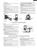
DAMPER OPEN-CLOSE MECHANISM
Usually, the damper is in the open position except during
convection cooking. Damper position is set automatically
by damper motor, damper switch, motor cam and damper
shaft. These components are operated by a signal that
judges if microwave cooking or convection cooking opera-
tion is selected by the control unit.
Microwave Cooking:
Damper is in the open position, because a portion of cooling
air is channelled through the cavity to remove steam and
vapors given off from the heating foods.
It is then exhausted at the top of the oven cavity into a
condensation compartment.
Convection Cooking:
Damper is in the closed position, so that no hot air will be
allowed to leak out the oven cavity.
Damper Operation
1. When power supply cord is plugged in:
1-1. When power supply cord is plugged in, a signal is
sensed in the control unit, and operates shut-off
relay (RY4).
1-2. Contacts of shut-off relay (RY4) close, the damper
motor is energized, opening the damper door.
1-3. When the damper is moved to the open position by
the damper cam the damper switch is closed (ON
position).
1-4. The signal from damper switch is re-sensed in the
control unit and shut-off relay (RY4) is turned off.
1-5. The 120 volts A.C. to the damper motor is removed
and the motor turns off.
2. When oven is microwave cooking:
Damper is in the open position.
3. When oven is convection cooking:
3-1. Damper motor is energized by touching the
convection, temperature and START pads.
3-2. When damper is in the closed position (damper
switch is OFF), its signal is sensed by the control
unit, and shut-off relay (RY4) is de-energized.
3-3. The damper is held in the closed position during the
convection cooking operation.
3-4. At the end of the convection cooking, shut-off relay
(RY4) is energized, and the damper is returned to
DAMPER DUCT
DAMPER
DAMPER CAM
DAMPER MOTOR
DAMPER SWITCH
DAMPER SHAFT
Summary of Contents for VMOC206SS
Page 3: ...3 Notes...


