27
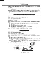
POSITIVE LOCK
®
CONNECTOR (NO-CASE TYPE) REMOVAL
Push the lever of positive lock
®
connector. Pull down on the
positive lock
®
connector.
CAUTION: WHEN YOU CONNECTING THE POSITIVE
LOCK
®
CONNECTORS TO THE TERMINALS,
INSTALL THE POSITIVE LOCK
®
SO THAT THE
LEVER FACES YOU.
Figure C-1. Positive lock
®
connector
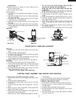
CONVECTION MOTOR REMOVAL
1. Disconnect oven from power supply and remove outer case.
2. Discharge the high voltage capacitor.
3. Disconnect wire leads from the convection motor. Remove
the convection fan belt.
4. Remove two (2) screws holding the convection motor
mounting angle to the heater duct and base cabinet.
5. Take out the convection motor assembly from the unit.
The convection motor assembly is now free.
6. Remove two (2) screws and nuts holding the motor to
mounting angle.
7. Remove pulley (M) from the motor shaft. Convection
motor is now free.
HIGH VOLTAGE RECTIFIER ASSEMBLY REMOVAL
1. Disconnect oven from power supply and remove outer
case.
2. Discharge the high voltage capacitor.
3. Remove one (1) screw holding the rectifier assembly to
the capacitor holder.
4. Disconnect the rectifier assembly from the capacitor and
1. Disconnect the oven from power supply.
Remove the turntable tray, and the turntable support out
of the oven cavity.
2. Turn the oven upside down and remove one (1) screw
holding the turntable motor cover to the base plate and
take off the turntable motor cover.
3. Disconnect wire lead from the turntable motor.
4. Remove the two (2) screws holding the turntable motor
TURNTABLE MOTOR REMOVAL
and coupling mounting plate to the oven cavity bottom.
5. Turntable motor, Coupling mounting plate and Thermal
protection plate bottom will be free.
DAMPER ASSEMBLY REMOVAL
1. Disconnect oven from power supply and remove outer
case.
2. Discharge the high voltage capacitor.
3. Disconnect wire leads from damper motor and damper
switch.
4. Remove two (2) oven side screws holding damper motor
angle to thermal protection plate (right).
5. Damper assembly is free.
6. Remove one (1) screw holding damper motor to damper
motor angle and one (1) screw holding damper switch
to damper motor angle.
7. Damper motor and switch are free.
magnetron.
CAUTION: WHEN REPLACING THE SILICON RECTI-
FIER ASSEMBLY, THE GROUND SIDE TER-
MINAL MUST BE SECURED FIRMLY WITH A
GROUNDING SCREW.
3. Disconnect the high voltage wire leads and rectifier
assembly from high voltage capacitor and magnetron.
4. Disconnect filament lead of transformer from high voltage
capacitor.
HIGH VOLTAGE CAPACITOR REMOVAL
1. Disconnect oven from power supply and remove outer case.
2. Discharge the high voltage capacitor.
5. Disconnect high voltage wire lead of capacitor from
transformer.
6. Remove one (1) screw and washer holding the rectifier
from the capacitor holder.
7. Remove one (1) screw holding the capacitor holder to
the rear cabinet.
8. Remove the capacitor from the holder.
Terminal
Push
Pull down
1
2
Lever
Positive lock®
connector
Summary of Contents for VMOC206SS
Page 3: ...3 Notes...


