background image


Revision: G 
Version:  May 26, 2010 
File:  

[201175-F-01-01.doc] 


U

U

s

s

e

e

r

r

s

s


M

M

a

a

n

n

u

u

a

a

l

l


WARNING: The information that is printed within this manual is vital for the correct use of the 
equipment; please read it carefully before use. 

Summary of Contents for Arcovis 3000

Page 1: ...on May 26 2010 File 201175 F 01 01 doc U Us se er r s s M Ma an nu ua al l WARNING The information that is printed within this manual is vital for the correct use of the equipment please read it caref...

Page 2: ...User s Manual ARCOVIS 3000 S R Villa Sistemi Medicali File 201175 G 01 01 doc This page is intentionally left blank...

Page 3: ...7 Operative messages 20 2 8 Alarm messages 21 2 9 Safety devices 23 3 UNIT USE 24 3 1 Transport 24 3 2 Connection between monitor trolley mobile stand 25 3 3 Connection between Footswitch Mobile Stan...

Page 4: ...ust not for any reason be moved modified or omitted The monitor trolley key switch may only be activated by authorized personnel and only during the use of the system Once system use has been complete...

Page 5: ...any examination the patient must remove earrings glasses necklaces and whatever could reflect the laser beam and be printed on the image Don t clean the openings of the laser targeting devices with t...

Page 6: ...ll the necessary protective precautions have been taken During the use of x rays personnel present in the room must comply with the following rules concerning protection against ionizing radiation Whe...

Page 7: ...cycle of materials that compose the unit The abusive disposal of the product from the user implies the application of administrative sanctions according to the Standards in force of the unit installat...

Page 8: ...able to be used for x ray examinations and in particular for radioscopy radiography and diagnosis dedicated to Traumatology Pediatrics Simple interventional radiology Pace Maker implantation Operating...

Page 9: ...nerators IEC 60601 2 28 1st edition Tube housing groups IEC 60601 2 32 1st edition Mechanical safety aspects ISO 14971 2000 Risk analysis CEI EN 60825 1 2nd edition Laser equipment safety ARCOVIS 3000...

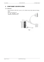
Page 10: ...g 8 76 Rev A File 201175 G 01 01 doc 2 COMPONENT IDENTIFICATION 2 1 Overview The unit ARCOVIS 3000 S R is made up of two different parts Mobile Stand and Display Station Mobile stand consisting of C A...

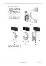
Page 11: ...ems with CCD 0 5K x 0 5K Fig 2 Low Profile Base Trolley with two LCD monitors 19 for video systems 0 5K2 Fig 3 High Profile Base Trolley with two monitors 18 for video systems 1K2 Fig 4 High Configura...

Page 12: ...n mobile image intensifier and monitor trolley Image intensifier Focus position Collimator Monobloc Outlet for the fluoroscopy footswitch connector Handles for the arm sliding Handle for the horizonta...

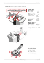
Page 13: ...p Movement 220mm 3 Brake for the orbital arm rotation Movement 123 90 33 Fig 8 4 Brake for the overview movement of the arm group Movement 12 5 1 Driving handle and rear wheels braking Fig 9 Pos 1 bra...

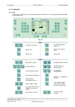
Page 14: ...on 1 Shutters diaphragm rotation Image enlargement Shutters diaphragm closing opening Horizontal image reversal Iris diaphragm closing opening Image edges enhancement Motion Detector unavailable funct...

Page 15: ...at the same time for approximately 4 seconds clearing time from 10 sec to 2 min The keyboard can be placed under the unit keyboard unit with monitor aboard or on the highest shelf of the Base Trolley...

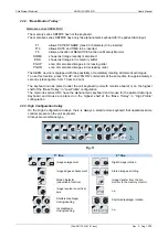
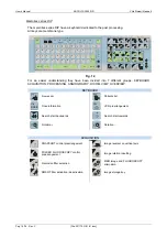
Page 16: ...F1 F2 F3 F4 F5 F6 F7 F8 F9 F10 Del DOSE Fig 12 For an easier understanding they have been divided into 7 different groups KEYBOARD ACQUISITION PROCESSING ANGIOGRAPHY DICOM VIEW OVERVIEW KEYBOARD New...

Page 17: ...on of the subtraction between images Angiographic acquisition rate selection 3 images per second Mask acquisition key Angiographic acquisition rate selection 6 images per second SHIFTING PIXEL functio...

Page 18: ...e alphanumeric keyboard and the mouse for the patient data input All keys are membrane type Pause Screen Print Del Lock Num E n t e r Ctrl Ctrl F1 Scroll Lock Alt 0 1 2 3 4 5 6 7 8 9 1 2 3 4 5 6 7 8 9...

Page 19: ...ositive on white background for the non active function in negative on black background for the active function Note the box with the dose indication is displayed only if the dosimeter is installed an...

Page 20: ...pedal a step Fluoroscopy mode snapshot control high contrast exposure with reduced background noise Fig 13 2 5 Handswitch for radiography fluoroscopy control The control handswitch is made of a two st...

Page 21: ...ual File 201175 G 01 01 doc Rev A Pag 19 76 2 6 Monitor Trolley Unit ARCOVIS 3000 S R with monitor aboard Unit ARCOVIS 3000 S R Low Profile Base Trolley Unit ARCOVIS 3000 S R High Profile Base Trolley...

Page 22: ...It s possible to exceed this limit and proceed with the x rays emission only in fluoroscopy mode till intervention of monobloc thermal security This choice must be performed by Service personnel and...

Page 23: ...o on to work Call Service to perform the planned maintenance REAL TIME CLOCK ERROR The system clock does not work Press the ALARM RESET key in order to go on to work Warning This function results part...

Page 24: ...ect and reconnect the footswitch In case the error persists call Service STARTER FAULT Only rotating anode Error in the circuit of the rotating anode Switch the unit OFF wait for some seconds and swit...

Page 25: ...m emergency push button placed on the console pos 2 It allows to stop the UP DOWN arm movement in case of danger In order to restore the UP DOWN movement rotate clockwise the push button body A remova...

Page 26: ...POSITION AT 0 2 ARM ROTATION AT 0 3 HORIZONTAL POSITION OF THE ARM GROUP IT IS ALL BACK 4 ORBITAL POSITION OF THE ARM AT 0 5 VERTICAL POSITION OF THE ARM GROUP IT IS ALL DOWN 6 ALL THE SAFETY SYSTEMS...

Page 27: ...ionable from the unit side On High Configuration trolley the cable is sectionable both from the unit side and the trolley side FOR A CORRECT CONNECTOR INSERTION HOLD THE SOCKET CONNECTOR IN ORDER TO M...

Page 28: ...at indicates the unit ON a lamp that indicates the x ray emission a door opening contact that stops the x ray emission The connection is performed through a multipolar connector with locking on ring n...

Page 29: ...or trolley only for the version with monitor trolley Connect the unit to the mains and put the magneto thermic switch in I position Insert the ON key and rotate it clockwise in WAIT position Rotate cl...

Page 30: ...e in WAIT position Turn the switching ON key clockwise in START position and release it the switching ON led will light up on the trolley control panel The trolley is powered and it can work even with...

Page 31: ...nt unit leg the vertical travel is limited downwards It is possible to exceed this limit by pressing at the same time the down key placed on the control panel and the Enable Down push button placed ne...

Page 32: ...ecautions against radiation have been activated Before performing an examination ensure that the residual exposure time indication is enough to the complete realization of diagnostic investigation 3 6...

Page 33: ...modify the parameters 1 2 mA curve selection When the key is selected the STANDARD curve with the halved mA values is used Selection of the MANUAL mode 3 6 2 Indication of the residual Fluoroscopy ti...

Page 34: ...e initial 5 minutes and by stopping the audible signal if it is in working condition After 10 minutes of continuous fluoroscopy the x ray emission is interrupted This supplementary time is resetting a...

Page 35: ...kV and mAs value must be set by the operator The exposure parameters variation allows to modify the image quality at the discretion of the operator X ray emission LEDs on the keyboard and on the monit...

Page 36: ...quirements HiPower Radiography selection key It appears only if the set mAs are lower than 2 2mAs Put the cassette holder at the input of the I I tube by coupling the two fixed locks and by locking th...

Page 37: ...for slim or sturdy patient is selected the icon of the key in negative appears Data storage key The proposed data can be modified at pleasure by the user If the storage function is enabled in the USER...

Page 38: ...hutter diaphragm automatically Rotate the position of the parallel shutters diaphragm Alternate the various fluoroscopy modes simply by passing from a pedal to the other one of the fluoroscopy footswi...

Page 39: ...upplied with the unit The DTU RJ 45 plug for connector is present only on the trolleys showed in the following figure For the operation of transfer or printing refer to the DTU User s Manual Wi Fi Tra...

Page 40: ...e the icon VOLUME Intensity of the buzzer volume from 0 to 100 It can be modified with the keys INC DEC aside the icon It is not possible to modify the volume of the x ray passage signals APR Storage...

Page 41: ...luoroscopy mode with relative resetting key Tot Rad Esposure Counter of the total exposures number in Radiography mode with relative resetting key Install date Unit installation data with relative res...

Page 42: ...mains supply it is necessary to perform first the correct shutdown of the DTU system Only after the DTU shutdown proceed with the unit switching OFF 1 Position the mobile image intensifier in parking...

Page 43: ...o the parts wear Regular checks and maintenance are necessary to protect the patient and the operator from damage due to the mechanical parts breakage The correct adjustment of the electro mechanical...

Page 44: ...from the mains before cleaning it Ensure that no liquid seeps into the unit so as to avoid short circuiting or corroding the electrical and electromechanical parts To clean enameled and aluminium surf...

Page 45: ...OVIS 3000 S R User s Manual File 201175 G 01 01 doc Rev E Pag 43 76 5 TECHNICAL DATA 5 1 Labels and symbols 5 1 1 Unit labels Pos 1 S N Label Pos 2 WEEE Label Fixed Anode Version All versions Rotating...

Page 46: ...44 76 Rev E File 201175 G 01 01 doc 5 1 2 Monitor trolley labels Pos 1 S N label present only on versions with monitor trolley Pos 2 WEEE label Fig 20 Fig 21 5 1 3 Monobloc labels Pos 1 S N label Fix...

Page 47: ...e image intensifier Codes present on the label in relation to the installed I I tube type Brand THALES TOSHIBA I I Tube type 9 6 4 TH 9428 HP2 H542 VR13 E5764SDS T1 Power supply type TH 7195 UP 33350...

Page 48: ...Equipotential node MAIN label WHEEE label Brakes lock release label External connections Monitor connection only version with monitor aboard Footswitch Hands squashing hazard Fluoroscopy and radiogra...

Page 49: ...ssory 5 1 7 MONITOR SYMBOLS Image contrast Image brightness on off push 5 1 8 FLUOROSCOPY FOOTSWITCH SYMBOLS Fluoroscopy control Image storage Pulsed fluoroscopy control Boost SNAPSHOT 5 2 Environment...

Page 50: ...ous oxide 5 3 1 RADIOLOGICAL DATA Description Fixed Anode Version Rotating Anode Version Generator power in DC current IEC 60601 2 7 2 5kW 100kV 100kV 25mA 100ms 3 5kW 100kV 35mA 91ms mAs 2 2 230Vac 5...

Page 51: ...oroscopy time for fixed anode version The values indicated in the graph refer to the trends calculated from the software safety procedures that are preventive concerning the bimetallic contact inside...

Page 52: ...roscopy time for rotating anode version The values indicated in the graph refer to the trends calculated from the software safety procedures that are preventive concerning the bimetallic contact insid...

Page 53: ...7 DASM Fields dimension DF 100cm 39 round field delimitation elliptical field delimitation 5 23cm 0 23cm Leakage radiation EN60601 1 3 par 29 204 3 40mR h Inherent filtration EN60601 1 3 0mm Classific...

Page 54: ...ity 500kJ 670kHU 600kJ 800 kHU Thermal safety 57 C 3 C Compensation lung 410cm3 Continuous thermal dissipation 75W 102 HU sec 6120 HU min Max housing temperature 60 C X ray tube filament power supply...

Page 55: ...Villa Sistemi Medicali ARCOVIS 3000 S R User s Manual File 201175 G 01 01 doc Rev D Pag 53 76 Monobloc RX I 40S 3 5 RF dimensions...

Page 56: ...kVP Max filament current 4 5A Nominal foci dimension Small focus Large focus 0 5mm 1 5mm Nominal anodic power Small focus Large focus 800W 4000W Anode material Tungsten Anode inclination angle 12 Ther...

Page 57: ...Villa Sistemi Medicali ARCOVIS 3000 S R User s Manual File 201175 G 01 01 doc Rev E Pag 55 76 Monobloc I 40R 5 RF dimensions...

Page 58: ...foci dimension Small focus Large focus 0 3mm 0 6mm Nominal anodic power Small focus Large focus 5kW 17kW Anode material Rhenium Tungsten Molybdenum Anodic diameter 64mm Anode inclination angle 10 Ther...

Page 59: ...l Half value layer 110kV Half value layer 120kV 5 3 5 TOTAL UNIT FILTRATION Description without DAPMeter with DAPMeter Monobloc 1 4 mmAl 1 4 mmAl Collimator 0 mmAl 0 mmAl Permanent additional filter 1...

Page 60: ...n time for the best image quality Other features as per Continuous Fluoroscopy Camera 1K2 Description Fixed Anode Version Rotating Anode Version Small focus IEC 336 0 5mm 0 3mm Exposure frequency sele...

Page 61: ...g Anode Version APR 1 Fine anatomic parts or for paediatric use 40kV 0 7mA 80kV 6 4mA 110kV 6 6mA 40kV 0 7mA 80kV 6 4mA 120kV 6 6mA APR 2 lungs 40kV 0 5mA 80kV 7mA 110kV 6mA 40kV 0 5mA 80kV 7mA 120kV...

Page 62: ...7 00 12 0 90 7 70 3 85 6 40 6 50 12 0 100 7 80 3 90 6 40 6 25 11 0 110 8 00 4 00 6 60 6 00 10 0 120 8 00 4 00 6 60 5 50 9 00 kV mA relationship of camera 1K2 kV mA Fixed Anode Version Standard mA 1 2...

Page 63: ...0 mAS from 101 to 120kV in 42 steps curve R 20 mAs range 115Vac 1 90 mAs from 40 to 100kV 1 80 mAS from 101 to 110kV 115Vac 1 90 mAs from 40 to 100kV 1 71 mAs from 101 to 120kV 230Vac 35 mA fixed from...

Page 64: ...seful Input Field Size 215 160 120 mm Typical Resolution Central 48 56 64 lp cm Conversion Factor Cd m 2 mR s 1 240 120 60 Contrast Ratio 23 1 25 1 30 1 Integral Image Distortion 4 2 1 Differential Di...

Page 65: ...correction 0 4 o 1 Automatic video level compensation Yes Dynamic contrast Shading Yes Video output A D converter 10 bit Power supply 24Vdc 20 20W Control Unit Dimensions 226x120x46 mm 0 550Kg Camera...

Page 66: ...ls 256 x 3 768 levels 16 7 Mil colors Brightness Max luminance 350cd m 2 750 cd m 2 typical 800 cd m 2 typical 250 cd m 2 typical Aspect Ratio 4 3 4 3 4 3 4 3 Response time 25ms 40ms 18ms 18ms Video S...

Page 67: ...Digital rotation in real time YES YES YES Vertical image Inversion YES in combination with the rotation YES in combination with the rotation YES in combination with the rotation Horizontal image inve...

Page 68: ...ition rate YES 1 3 6 fps Recursive Filter Noise reduction OFF 2 4 8 16 YES 2 4 8 16 Left and Right image inversion YES Real time Digital rotation without X Ray on memory YES Cine loop review YES Progr...

Page 69: ...in ram or 50 000 images on hard disk dicom Gamma correction Yes digital Recursive filter smart Yes Digital image rotation LIH Yes Edge enh 3x3 Yes Dynamic range 1 2 1 3 1 4 1 5 Post Processing Grey sc...

Page 70: ...s Max opacity fluoroscopy acquirement Yes Subtraction in real time with manual automatic mask Yes Programmed acquirement sequences Yes 3 6 12 25 fps Post Processing Image horizontal and vertical inver...

Page 71: ...oth ways with Dicom units present on the network Dicom STORAGE SCU It allows to send the images to a Dicom server for filing Dicom WORKLIST SCU It queries and receives from a Dicom server the patients...

Page 72: ...ose meter S Sprint s on unit Collimator with iris and parallel shutter Equipotential node cable lg 300 External interlocks kit Movement handles on C arm Movement handle on I I tube Laser targeting dev...

Page 73: ...nter Sony UP970CE or UP990CE Description Data Print method Thermal printer with multi image picture UP 960 only 2 images Sublimation print not available Thermal head 1280 elements Grey levels 256 leve...

Page 74: ...ll bit load impedance 47 kOhm ILINK DV IN ILINK 6 pin x1 IEEE1394 Remote Control RS 232C x1 D sub 9 pin USB 2 2 x1 Full Speed Remote 2 x1 stereo mini jack for connection with optional FS 20 foot switc...

Page 75: ...COVIS 3000 S R User s Manual File 201175 G 01 01 doc Rev A Pag 73 76 6 MECHANICAL DATA 6 1 C arm unit dimensions with I I 9 6 2 Axis and interventionist reference point Interventionist reference point...

Page 76: ...edicali Pag 74 76 Rev A File 201175 G 01 01 doc 6 3 Base Trolley monitor trolley dimensions max admissible weights on the single shelves 2 kg 10 kg In the version Low Profile Base Trolley for systems...

Page 77: ...Villa Sistemi Medicali ARCOVIS 3000 S R User s Manual File 201175 G 01 01 doc Rev A Pag 75 76 6 4 Dimensions of High Configuration monitor trolley...

Page 78: ...3 E C arm group overview Manual 12 5 F Useful space 770 mm 30 31 in G C arm depth 690 mm 27 17 in H S I D 971 mm 38 23 in Rotating Anode 988 mm 38 90 in Fixed Anode I Focus Skin Distance 200 mm 7 87 i...

Page 79: ...ification to the small focus from 0 6 to 0 5 on the OX 100 5 insert concerning the fixed anode monobloc and various corrections in the document Updated description at point 3 of the Operative Messages...

Reviews: