User's Manual
ARCOVIS 3000 S/R
Villa Sistemi Medicali
Pag. 26/76 - Rev. A
[File:201175-G-01-01.doc]
3.3. Connection between Footswitch – Mobile Stand
The connection between these parts of ARCOVIS 3000 S/R is performed through a
connector with press connection.
•
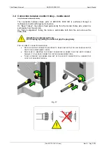
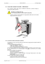
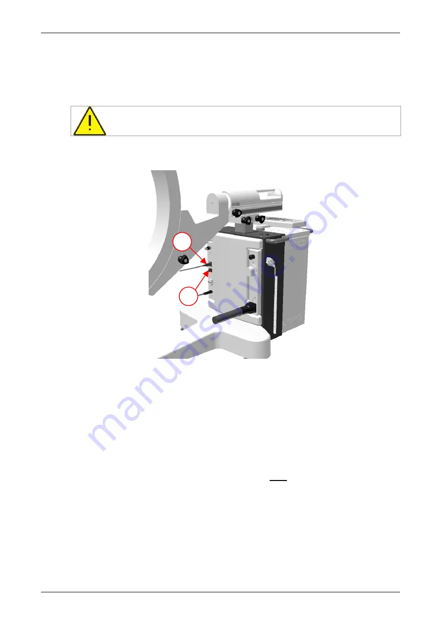
insert the connector of the footswitch in the appropriate outlet present on the mobile
image intensifier (Fig. 18 pos. A);
Fig. 18
3.3.1. Connection for External Interlocks (optional)
It is possible to use the unit as fixed position so that some warning signals are repeated outside the
operative room.
In detail the repeated warning signals are for:
• a lamp that indicates the unit ON
• a lamp that indicates the x-ray emission
• a door opening contact that stops the x-ray emission.
The connection is performed through a multipolar connector with locking on ring nut (Fig. 18 pos.
B). The prearrangement of the external signals wiring
must
be performed by the technical
personnel.
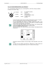
For a correct connection it is necessary to:
• ensure that the unit is OFF;
• remove the terminal board closing cap;
• insert the connector of “external interlocks” in the proper socket present on the mobile
image intensifier;
• ensure that the connector is screwed tight.
In order to remove the connection it is necessary:
• unscrew and remove the cable connector
• apply again the closing cap in the terminal board.
Handle the connectors with care.
Don't unplug by pulling the cable but grip the plug body.
B
A

