122648 / 0438
4 / 4
122648 / 0438
3 / 4
Installation, user and maintenance
instructions, cookerhood, type 251-16
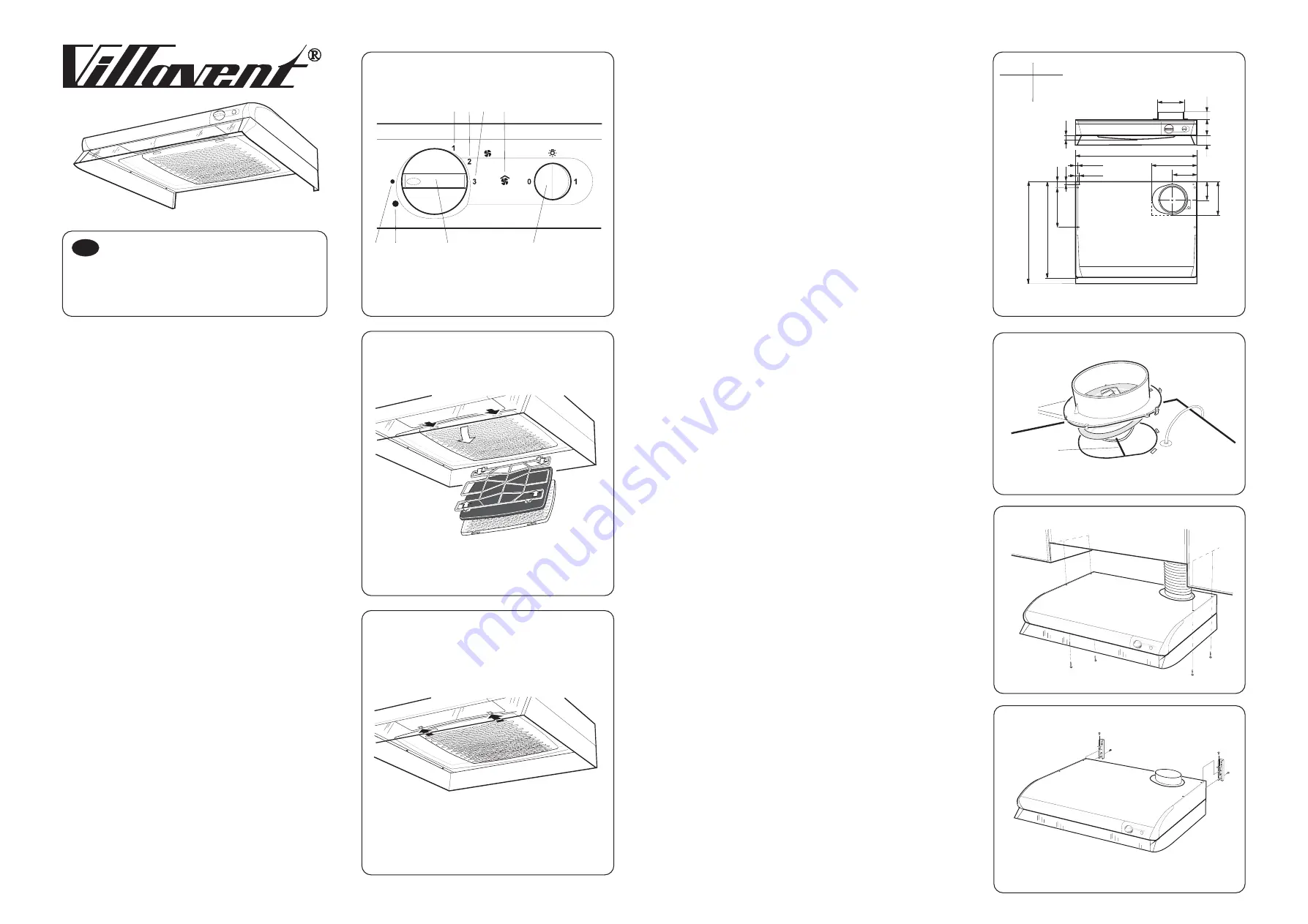
Operation, Fig. 1
Maintenance
Troubleshooting
A
B
1,2,3
4
5
6
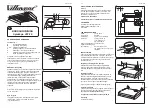
fig.2
Note! Build-up of grease and dust inside the
cookerhood increases the risk of fire.
Changing the fluorecent tube
fig.3
- Switch for fan speed/damper
- Light switch
- Fan speed control, 3 steps
with open damper
- Minimum ventilation
- Forced ventilation
- Light on indicates forced ventilation
Remove filter for cleaning at least twice a month,
. Soak the filter cloth and grill in warm soapy
water, and wipe clean the inside of the
cookerhood. The filter casette can alternatively
be washed in a dish washer. Let the filter dry
properly before replacing it.
To chane the fluorecent tube, open the lamp
cover as shown in
(socket G23).
Check the fuse. Test the fluorecent tube and that
the cookerhood is operating on all fan speeds.
Contact your local supplier for further assistance.
Flames under the cookerhood must be avoided.
Ensure sufficient fresh air supply to the room
where the cookerhood is installed.
Technical data:
Width:
50 or 60 cm
Dimensions:
See
El.connection: 230V
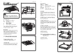
fig.4
~, 50Hz + earth
Light:
Fluorecent tube, 11 W socket G23
Max power:
300 W at 230 V
Voltage from
transformer:
80, 100, 130 or 145 V
(100 and 130 V are std. settings)
The installation must be made in accordance with
installation instructions for extract fan or regulations
from the authorities in force.
A duct connector is provided. Install the damper axis “ ”
in the opening under the damper lid. Ensure that the
clips “ ” get under the top plate. Snap the connector
into position.
The cookerhood is tobe installed above the stove. The
distance from electrical hob must be minimum 40 cm
and from a gas hob minimum 65 cm. The cookerhood
can be installed under a cupboard
or by means of
brackets (additional equipment),
.
See separate instructions.
See separate instructions.
Installation
The exhaust duct leaving the cookerhood must be
available for cleaning and made of non-flammable
material.
NOTE! Discharge air must not be lead into smoke-
extract duct. Which is connected to chimney, heating
furnace etc.
Installing the damper, fig.5
A
B
Installing the cookerhood
fig.6
fig 7
Electrical installation
NOTE! Electrical installation must be made by
authorised installer and in accordance with
regulations in force.
Adjusting the airflow
1 2 3
4
5
A
B
6
1
1
2
80
40
125
220
99
180
480
9,5
A
50
190
126
16
13
22
51
1
70
A
B
GB
Width
A
500
600
498
598
1
2
3
4
5
6
7


