9
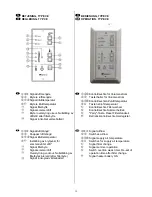
Fig. 3
BEDIENUNG (Fig. 3)
Die Anlage wird über eine integrierte und eine
oder mehrere Fernbedienungen mit folgenden
Funktionen betrieben:
Luftvolumenstrom (Ventilatordrehzahl)
Tasten für die Wahl von 3 Stufen. Erhöhen/
Senken der Drehzahl durch drücken der Tasten
(4) bzw (5). Die Leuchten(1), (2) und (3) zeigen
die eingestellte Stufe.
Min (1) kleinste Stufe. Während Ferien oder
wenn sich niemand im Haus aufhält.
Norm (2) normale Stufe an das Gebäude
angepaßt. Siehe Montageanleitung,
Inbetriebnahme/Grundeinstellung.
Max (3) größte Stufe. Kann eingestellt werden,
wenn ein höherer Luftwechsel nötig ist.
Zulufttemperatur
Tasten für die Wahl der Temperatur in 5 Stufen.
Die Zulufttemp. wird erhöht/gesenkt durch drücken
der Tasten (9) bzw (10). Die Leuchten (6), (7) und
(8) zeigen die Eingestellte Zulufttemperatur.
Stufe 1 Lampe (6) leuchtet
(Min.)
Stufe 2 Lampen (6) + (7) leuchten
Stufe 3 Lampe (7) leuchtet
Stufe 4 Lampen (7) + (8) leuchten
Stufe 5 Lampe (8) leuchtet
(Max.)
OPERATION (Fig. 3)
The unit is equipped with an integrated
control panel. In addition operation can be
made from one or more remote controllers,
all with the following functions:
Airflow (Fan speed)
Switches for choice of airflow in 3 steps.
Increase/decrease fan speed by pressing the
switches (4) and (5) alternatively. Lamp signals
(1), (2) and (3) show set airflow.
Min (1) Minimum ventilation. To be used
during holidays or when the building is
not in use.
Norm (2) Normal ventilation adapted to the
building. See installation instr.,
Commissioning.
Max (3) Forced ventilation. Is used when extra
airflow is required.
Supply air temperature
Switches for choice of inlet air temperature in 5
steps. Supply air temperature is increased/ de-
creased by pressing switch (9) and (10)
alternatively. Lamp signals (6), (7) and (8) show
set supply air temperature.
Step 1 Lamp (6) lights
(Min.)
Step 2 Lamp (6) and (7) light
Step 3 Lamp (7) lights
Step 4 Lamp (7) and (8) light
Step 5 Lamp (8) lights
(Max.)
Summary of Contents for VR-400 EV/B
Page 20: ...20...


