CONTENTS
Introduction 1
Special Information
2
Special Mechanical Seals
2
Maintenance 2
Disassembly 3
Assembly 5
Thrust Bearing Adjustment
7
Installation of Carbon Graphite Bushings
7
Pressure Relief Valve Instructions
7
INTRODUCTION
The illustrations used in this manual are for identification
purposes only and cannot be used for ordering parts. Obtain
a parts list from the factory or a Viking® representative.
Always give complete name of part, part number and
material with model number and serial number of pump
when ordering repair parts. The unmounted pump or pump
unit model number and serial number are on the nameplate
secured to the pump.
In the Viking model number system, basic size letters are
combined with series number (4195 and 495), indicating both
the unmounted or mounted pump units.
Model Number Chart
VIKING PUMP INC. •
A Unit of IDEX Corporation •
UNMOUNTED PUMP
UNITS
Foot Mounted
GG 4195
HJ 4195
HL 4195
AS 4195
Units Are Designed By The
Un-Mounted Pump Model
Numbers Followed By A
Letter(s) Indicating Drive Style.
AK 4195
AL 4195
D = Direct Drive
Flange Mounted
GG 495
M = Horizontal Direct Drive
HJ 495
HL 495
IM = Vertical In Line Direct Drive
AS 495
AK 495
AL 495
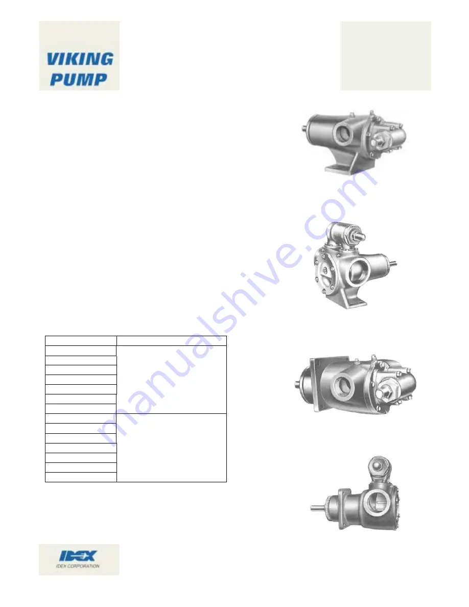
FIGURE 2
AS, AK and AL 4195 SERIES
Foot Type Unmounted Pump with Tapped Ports
FIGURE 1
GG. HJ and HL 4195 SERIES
Foot Type Unmounted Pump with Tapped
TECHNICAL SERVICE MANUAL
HEAVY DUTY PUMPS
SERIES 4195 and 495
SERIES GG - AL
SECTION TSM
144
PAGE
1 OF 9
ISSUE
B
FIGURE 4
AS, AK and AL SIZE 495 SERIES
Unmounted Pump with Tapped Ports
FIGURE 3
GG. HJ and HL SIZE 495 SERIES
Unmounted Pump with Tapped Ports
This manual deals only with Series 4195 and 495 Heavy
Duty Pumps. Refer to Figures 1 thru 14 for general
configuration and nomenclature used in this manual. Pump
specifications and recommendations are listed in Catalog
Section 144, Series 4195 and 495 Heavy Duty Pumps.
Summary of Contents for VSM 71-701
Page 1: ...1 VPN 35391S February 2006 Rev 05 Price 60 00...
Page 2: ...2...
Page 20: ...20...
Page 52: ...53 Pre Start Up Check List...
Page 99: ...99 Recommended Spare Parts List...
Page 104: ...104 Gate Rotor...
Page 110: ...110 Main Rotor VSS...
Page 112: ...112 Main Rotor VSR...
Page 114: ...114 Slide Valve Cross Shafts and End Plate...
Page 118: ...118 Capacity Slide Volume Slide Carriage Assembly Slide Valve Carriage Assembly...
Page 134: ...134 Miscellaneous Frame Components VSS Screw Compressor VSR Mini Screw Compressor...
Page 138: ...138 C FlangeAdapter Components 630 620 610 640 601 641 630 601 620 610 640 641 642 650 651...
Page 140: ...140 Replacement Parts Tools...
Page 144: ...144 GaterotorAssembly...
Page 148: ...148 Main Rotor Slide Valve Cross Shafts and End Plate Models 71 401 Only Counter clockwise...
Page 152: ...152 Main Rotor Slide Valve Cross Shafts and End Plate Model 501 701 Only Clockwise...
Page 154: ...154 Volume Ratio Capacity Slide Carriage Assembly Slide Valve Carriage Assembly...
Page 158: ...158 Miscellaneous Frame Components Model VSM 501 701 Model VSM 71 401...
Page 160: ...160 Replacement Parts Accessories Housing Accessories C Flange Assembly...
Page 166: ...166 Haight Pumps...
Page 170: ...3 Refrigerating Specialties Division...
Page 236: ......
Page 237: ......
Page 238: ......
Page 243: ......
Page 244: ...168...


