Page 2
/ BULLETIN 10-11
Liquid subcooling is provided by the following
methods:
1. In the condenser
2. Suction – liquid heat exchanger
3. Special devices
Method 1
– will provide sufficient subcooling for the simple short-
coupled system that has only moderate liquid line pressure drop.
Method 2
– will usually not provide more than 20°F subcooling on
air conditioning systems operating at normal head pressures. The
amount of subcooling will depend on the design and size of the heat
exchanger and on the operating suction and discharge pressures.
Method 3
– may be used to provide considerable subcooling
required for systems with excessive vertical lift. The following
special devices are the most commonly used methods:
■
Water coils in heat exchange relationship with the liquid line.
■
Separate refrigeration system.
■
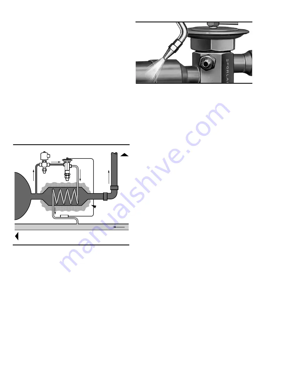
Special heat exchanger which uses a portion of the refrigerant to
cool the main body of liquid. See Figure 1.
Ordinarily the conventional suction-liquid heat exchanger is installed
near the evaporator, where the suction vapor is the coldest, to re-
condense any vapor in the liquid line. When the primary purpose of
the heat exchanger is to prevent the formation of flash gas – particu-
larly on systems that have a long liquid line or excessive vertical lift
– install the heat exchanger near the receiver
before the vertical
lift occurs
. (This also applies to the special devices described in
Method 3). Because vapor in the liquid line considerably increases
friction losses, the total pressure drop available across the expansion
device on these types of systems is reduced. Also, the suction line and
liquid line should be carefully insulated to minimize heat gain if
subcooled below ambient temperature.
Important
Preventing the formation of vapor in liquid lines having high pressure
losses does not eliminate the requirement that an adequate pressure
drop must be available across the TEV. The capacity tables show
valve capacities at pressure drops lower than normal. For TEV
application data and capacities at pressure drops below those listed,
consult Sporlan Valve Company
.
Solder Techniques
It is not necessary to disassemble solder type valves when soldering
to the connecting lines. Any of the commonly used types of solders,
e.g., 95-5, Sil-Fos, Easy-Flo, Phos-Copper, Stay Brite 8 or equiva-
lents may be used for copper to copper connections. When soldering
a brass refrigerant distributor to the valve, appropriate solders for
these connections, such as 95-5, Easy-Flo, Stay Brite 8 or equivalents
must be used. It is important however, regardless of the solder used,
to direct the flame away from the valve body and avoid excessive
heat on the diaphragm, Figure 2. As an extra precaution, a wet cloth
may be wrapped around the body and element during the soldering
operation.
This precaution will prevent overheating the valve body which could
damage the superheat spring and result in flood back problems. In
addition, the Type O, EBF/SBF, and EBS valve contain synthetic
parts which can be damaged due to overheating, resulting in poor
valve performance.
Bulb Location and Installation
The location and installation of the bulb is extremely important to the
proper performance of the system and care should be taken with its
final location.
Accepted principles of good suction line piping should be followed
to provide a bulb location that will give the best possible valve
control. When system manufacturers have piping recommendations
that differ from the general industry recommendations and Sporlan’s
suggestions shown in this section, those recommendations should be
used. When specific recommendations are not available, the sugges-
tions below should be used.
The bulb should be attached to a horizontal suction line at the
evaporator outlet (See Figures 3, 4, and 5) If the bulb cannot be
located in that manner, it may be located on a
descending
vertical
line only (as shown in Figure 5 for “pumpdown control”). The bulb
should never be located in a trap or downstream of a trap in the
suction line. Liquid refrigerant or mixture of liquid refrigerant and oil
boiling out of the trap will falsely influence the temperature of the
bulb and result in poor valve control.
On suction lines 7/8” OD and larger, the surface temperature may
vary slightly around the circumference of the line. On these lines, it
is generally recommended that the bulb be installed at 4 or 8 o’clock
on the side of the horizontal line, and parallel with respect to the
direction of flow. On smaller lines the bulb may be mounted at any
point around the circumference, however locating the bulb on the
bottom of the line is not recommended as an oil-refrigerant mixture
is generally present at that point. Certain conditions peculiar to a
particular system may require a different bulb location than normally
Figure 2
To Compressor
Main Liquid Line
Insulation
Main Suction Line
Receiver
Figure 1
Summary of Contents for VSM 71-701
Page 1: ...1 VPN 35391S February 2006 Rev 05 Price 60 00...
Page 2: ...2...
Page 20: ...20...
Page 52: ...53 Pre Start Up Check List...
Page 99: ...99 Recommended Spare Parts List...
Page 104: ...104 Gate Rotor...
Page 110: ...110 Main Rotor VSS...
Page 112: ...112 Main Rotor VSR...
Page 114: ...114 Slide Valve Cross Shafts and End Plate...
Page 118: ...118 Capacity Slide Volume Slide Carriage Assembly Slide Valve Carriage Assembly...
Page 134: ...134 Miscellaneous Frame Components VSS Screw Compressor VSR Mini Screw Compressor...
Page 138: ...138 C FlangeAdapter Components 630 620 610 640 601 641 630 601 620 610 640 641 642 650 651...
Page 140: ...140 Replacement Parts Tools...
Page 144: ...144 GaterotorAssembly...
Page 148: ...148 Main Rotor Slide Valve Cross Shafts and End Plate Models 71 401 Only Counter clockwise...
Page 152: ...152 Main Rotor Slide Valve Cross Shafts and End Plate Model 501 701 Only Clockwise...
Page 154: ...154 Volume Ratio Capacity Slide Carriage Assembly Slide Valve Carriage Assembly...
Page 158: ...158 Miscellaneous Frame Components Model VSM 501 701 Model VSM 71 401...
Page 160: ...160 Replacement Parts Accessories Housing Accessories C Flange Assembly...
Page 166: ...166 Haight Pumps...
Page 170: ...3 Refrigerating Specialties Division...
Page 236: ......
Page 237: ......
Page 238: ......
Page 243: ......
Page 244: ...168...


