BULLETIN 10-11 /
Page 3
recommended. In these cases the proper bulb location may be
determined by trial.
For satisfactory expansion valve control,
good thermal contact
between the bulb and suction line is essential. The bulb should be
securely fastened with two bulb straps, supplied with each expansion
valve, to a clean straight section of the suction line.
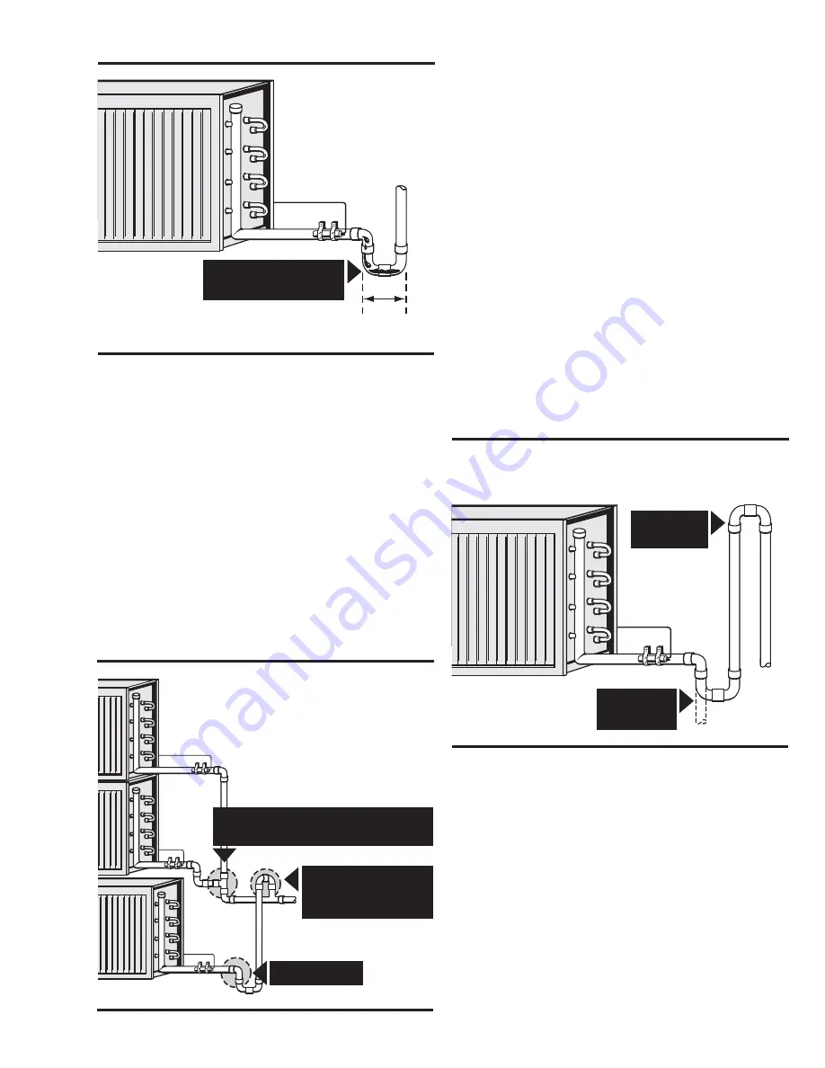
Recommended suction line piping usually includes a horizontal line
leaving the evaporator to which the TEV bulb is attached. This line is
pitched slightly downward, and when a vertical riser follows, a short
trap is placed immediately ahead of the vertical line, see Figure 3.
The trap will collect any liquid refrigerant or oil passing through the
suction line and prevent it from influencing the bulb temperature.
On multiple evaporator installations
the piping should be
arranged so that the flow from any valve cannot affect the bulb of
another. Approved piping practices including the proper use of traps
insures individual control for each valve without the influence of
refrigerant and oil flow from other evaporators.
For recommended suction line piping when the compressor is located
below the evaporator see Figure 5. The vertical riser extending to the
height of the evaporator prevents refrigerant from draining by gravity
into the compressor during the off-cycle. When a pumpdown control
is used the suction line may turn immediately down without a trap.
On commercial and low temperature applications
requiring
Sporlan Selective Charges C, Z, or X the bulb should be clamped on
the suction line at a point where the bulb temperature will be the same
as the evaporator temperature during the off-cycle. This will insure
tight closing of the valve when the compressor stops. If bulb insula-
tion is used on lines operating below 32°F, use non-water absorbing
insulation to prevent water from freezing around the bulb.
On brine tanks and water coolers, the bulb should be below the liquid
surface where it will be at the same temperature as the evaporator
during the off-cycle. When locating the bulb in a brine tank, paint it
and the capillary tubing with pitch or other corrosion resistant paint.
If, for practical reasons, the bulb must be located where its tempera-
ture will be higher than the evaporator during the off-cycle, a
solenoid valve must be used ahead of the TEV.
On air conditioning applications
having TEVs equipped with
VCP100 or VGA elements, the bulb may be located inside or outside
the cooled space or duct. The valve body should not be located in the
air stream leaving the evaporator. Avoid locating the bulb in the
return air stream unless it is well insulated.
External Equalizer Connection
For a complete explanation of when an externally equalized valve
should be used, refer to "equalization method," Bulletin 10-9. Valves
supplied with an external equalizer
will not operate
unless this
connection is made.
The equalizer connection should be made at a point that will most
accurately reflect the pressure existing in the suction line at the bulb
location. See Figure 6. Generally, the connection is immediately
downstream of the bulb. However, equipment manufacturers
sometimes locate them in return bends or suction headers that are
Compressor
ABOVE
Evaporator
Short as possible to minimize amount of oil.
Liquid and oil drains
away from bulb...
Figure 3
Multiple Evaporators
Above and Below Main Suction Line
Flow from upper valve cannot
affect bulb. . . . line free draining.
Inverted trap to
avoid oil draining
into idle evaporator.
Free draining.
Figure 4
Compressor BELOW
Evaporator
Pumpdown
Control
Without
Pumpdown
Figure 5
Summary of Contents for VSM 71-701
Page 1: ...1 VPN 35391S February 2006 Rev 05 Price 60 00...
Page 2: ...2...
Page 20: ...20...
Page 52: ...53 Pre Start Up Check List...
Page 99: ...99 Recommended Spare Parts List...
Page 104: ...104 Gate Rotor...
Page 110: ...110 Main Rotor VSS...
Page 112: ...112 Main Rotor VSR...
Page 114: ...114 Slide Valve Cross Shafts and End Plate...
Page 118: ...118 Capacity Slide Volume Slide Carriage Assembly Slide Valve Carriage Assembly...
Page 134: ...134 Miscellaneous Frame Components VSS Screw Compressor VSR Mini Screw Compressor...
Page 138: ...138 C FlangeAdapter Components 630 620 610 640 601 641 630 601 620 610 640 641 642 650 651...
Page 140: ...140 Replacement Parts Tools...
Page 144: ...144 GaterotorAssembly...
Page 148: ...148 Main Rotor Slide Valve Cross Shafts and End Plate Models 71 401 Only Counter clockwise...
Page 152: ...152 Main Rotor Slide Valve Cross Shafts and End Plate Model 501 701 Only Clockwise...
Page 154: ...154 Volume Ratio Capacity Slide Carriage Assembly Slide Valve Carriage Assembly...
Page 158: ...158 Miscellaneous Frame Components Model VSM 501 701 Model VSM 71 401...
Page 160: ...160 Replacement Parts Accessories Housing Accessories C Flange Assembly...
Page 166: ...166 Haight Pumps...
Page 170: ...3 Refrigerating Specialties Division...
Page 236: ......
Page 237: ......
Page 238: ......
Page 243: ......
Page 244: ...168...


