Page 4
/ BULLETIN 10-11
compatible with their specific design requirements. The difference
between the pressure at the equalizer connection and the suction
pressure at the bulb location should not exceed reasonable pressure
drop values. The values shown in Table 1 of Bulletin 10-9 can be
used as a guide in determining the value.
If any evaporator pressure or temperature control valves are located
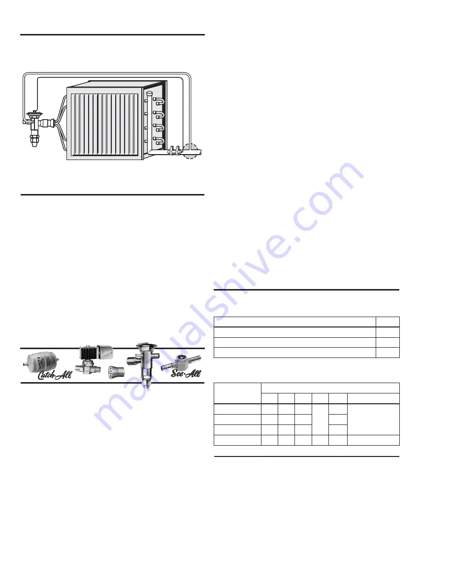
in the suction line at or near the evaporator outlet, the equalizer must
be connected on the evaporator side of these valves.
Driers, Strainers, and Accessories
Most Sporlan TEVs are equipped with built-in screens of varying
mesh sizes depending on the valve size and type. These strainers are
effective only in removing particles of scale, solder, etc. which could
obstruct the closure of the pin and seat.
Moisture and smaller particles of foreign materials are equally
harmful to the system and must be removed for peak system perfor-
mance. Field experience has proven that, without a doubt, most
expansion valve failures are due to the presence of dirt, sludge, and
moisture in the system. Furthermore, the performance and life of
other system components are also seriously affected by these foreign
materials. The Sporlan
Catch-All Filter-Drier
®
removes dirt,
moisture, acids, and sludge, and insures the circulation of clean, dry
refrigerant through the system at all times.
For all refrigeration and air conditioning applications we recommend
that a Sporlan Catch-All Filter-Drier be installed in the liquid line
ahead of the TEV. See Bulletin 40-10 for complete Catch-All Filter-
Drier specifications.
Further system protection is easily and inexpensively provided with
the installation of a Sporlan
See-All
®
. The See-All is a combination
liquid and moisture indicator that visually indicates if there is a
shortage of refrigerant in the liquid line, or if the moisture content of
the refrigerant is at a dangerous level. See Bulletin 70-10 for
complete See-All specifications.
Test Pressures and Dehydration
Temperatures
Inert dry gases such as nitrogen, helium or CO2 are often
used for leak detection
.
CAUTION:
Inert gases must be added to the system
carefully through a pressure regulator. Unregulated gas
pressure can seriously damage the system and endanger
human life. Never use oxygen or explosive gases.
Excessive test pressures can shorten the life of the TEV diaphragm.
Table 1 lists the maximum pressure that can safely be applied with
the expansion valve connected to the evaporator. These maximum
pressures are well above the minimum field leak test pressures for
low sides, listed by the ANSI/ASHRAE Standard 15-2001 or latest
revision.
The external equalizer line should be disconnected if there is any
possibility of exceeding the recommended maximum pressures
listed below.
If elevated temperatures are used to assist in dehydrating the system,
the TEV should not be exposed to temperatures exceeding those
shown in Table 2.
Table 2 refers to the maximum dehydration temperatures when the
bulb and valve body are subjected to the same temperature. On L, C,
Z, and X charges, 250°F maximum valve body temperature is
permissible
if the bulb temperature
does not exceed those
shown in the table.
Expansion Valve Adjustment
Each Sporlan TEV is thoroughly tested and set at the factory before
shipment. This factory superheat setting will be correct and no
further adjustment is required for the majority of applications.
However, there are many factors which can affect the performance of
a TEV. These factors are independently variable and all of them
cannot be compensated for in the design of a valve. When the
application or operating conditions require a different valve setting
due to one or more of the factors listed below, the valve may be
adjusted to obtain the required operating superheat. Therefore, an
adjusting stem is provided on all standard valves. The valve should
be set with the system as near as possible to design conditions.
Figure 7
1
e
l
b
a
T
s
e
r
u
s
s
e
r
P
t
s
e
T
e
d
i
S
w
o
L
m
u
m
i
x
a
M
e
p
y
T
e
v
l
a
V
g
i
s
p
O
ll
a
m
S
,
S
B
E
,
S
,
C
,
G
E
,
G
,
I
R
,
F
B
S
/
F
B
)
E
(
,
B
F
,
F
,
I
N
,
X
,
I
)
B
(
0
5
4
O
e
g
r
a
L
,
H
,
P
,
D
5
2
4
W
,
V
,
M
,
A
0
0
4
2
e
l
b
a
T
F
s
e
e
r
g
e
D
–
s
e
r
u
t
a
r
e
p
m
e
T
n
o
i
t
a
r
d
y
h
e
D
m
u
m
i
x
a
M
t
n
a
r
e
g
i
r
f
e
R
e
g
r
a
h
C
c
i
t
a
t
s
o
m
r
e
h
T
L
C
Z
X
A
G
V
s
e
i
r
e
S
P
Z
,
e
p
y
T
P
a
4
3
1
,
2
1
0
9
1
0
9
1
0
5
2
0
1
2
-
-
-
0
5
2
2
2
0
6
1
0
6
1
5
8
1
0
5
2
7
0
5
,
2
0
5
,
A
4
0
4
0
5
1
0
5
1
0
7
1
-
-
-
)
a
i
n
o
m
m
A
(
7
1
7
0
5
1
0
9
1
5
3
2
-
-
-
-
-
-
-
-
-
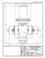
External Equalizer
Connection
It must be connected - NEVER CAPPED!
Must be free of crimps, solder, etc.
Figure 6
Summary of Contents for VSM 71-701
Page 1: ...1 VPN 35391S February 2006 Rev 05 Price 60 00...
Page 2: ...2...
Page 20: ...20...
Page 52: ...53 Pre Start Up Check List...
Page 99: ...99 Recommended Spare Parts List...
Page 104: ...104 Gate Rotor...
Page 110: ...110 Main Rotor VSS...
Page 112: ...112 Main Rotor VSR...
Page 114: ...114 Slide Valve Cross Shafts and End Plate...
Page 118: ...118 Capacity Slide Volume Slide Carriage Assembly Slide Valve Carriage Assembly...
Page 134: ...134 Miscellaneous Frame Components VSS Screw Compressor VSR Mini Screw Compressor...
Page 138: ...138 C FlangeAdapter Components 630 620 610 640 601 641 630 601 620 610 640 641 642 650 651...
Page 140: ...140 Replacement Parts Tools...
Page 144: ...144 GaterotorAssembly...
Page 148: ...148 Main Rotor Slide Valve Cross Shafts and End Plate Models 71 401 Only Counter clockwise...
Page 152: ...152 Main Rotor Slide Valve Cross Shafts and End Plate Model 501 701 Only Clockwise...
Page 154: ...154 Volume Ratio Capacity Slide Carriage Assembly Slide Valve Carriage Assembly...
Page 158: ...158 Miscellaneous Frame Components Model VSM 501 701 Model VSM 71 401...
Page 160: ...160 Replacement Parts Accessories Housing Accessories C Flange Assembly...
Page 166: ...166 Haight Pumps...
Page 170: ...3 Refrigerating Specialties Division...
Page 236: ......
Page 237: ......
Page 238: ......
Page 243: ......
Page 244: ...168...


