BULLETIN 10-11 /
Page 11
Note
: These Field Assembly Instructions apply in part to all Sporlan
TEVs. See Figure 9 for an “exploded” view of those models that can
be completely disassembled. When a TEV is to be disassembled for
inspection and cleaning, or for replacement of the thermostatic
element or the internal parts, the following information should be
reviewed for assistance.
Types F dated approximately C84 or earlier and Types I, BI, NI, RI,
FB manufactured prior to 1994 do not have replaceable elements nor
internal parts kits, but can be disassembled for inspection and
cleaning. Type F dated D84 or later, Type S valves dated B69 or later,
Type C valves dated C70 or later, and
ALL
Type G, X, (E)BF/SBF
and EBS valves employ packless pushrod construction and internal
parts are NOT available for use with them. However, their elements
can be replaced and they can be disassembled for inspection and
cleaning. Due to the single pushrod construction of the Type
(E)BF/SBF and EBS valves, only the bottom cap assembly, pin
guide, and superheat spring may be removed for inspection and
cleaning.
Early production of the Type F valve with the replaceable element
requires a 15/16"
thin jaw
, open end type element wrench such as a
Bonney 1230. Subsequent production of the Type F valve and all
Types (E)BF/SBF, I, BI, NI, RI, and FB valves require a 1"
thin jaw
,
open end type element wrench such as the one available from
Sporlan wholesalers. An open end wrench is necessary because of
limited space between the body and element of these valves.
Precautions must be taken in removing the KT-43 element (F) so the
element, body, or connections are not damaged by the wrenches.
While standard open end or adjustable wrenches fit the other element
sizes, the
thin jaw
type wrenches are also available for the other
element sizes: Bonney 1236 (1-1/8") for KT-53 elements, Bonney
1240 (1-1/4") for KT-83 elements, Bonney 1248 for KT-33 elements,
and Bonney 1252 for KT-63 and 7 elements.
Replaceable elements and internal parts kits are available for current
valves with
packed
pushrod construction:
Types P, H, M, D, and A.
Replaceable elements for Types O, V, W, and U are also available.
However, special field assembly instructions are included with their
internal parts kits.
Assembling Instructions
The following steps are necessary in properly disassembling,
inspecting, cleaning, and reassembling a TEV whether the valve is in
or out of the refrigerant piping.
1.
Before disassembling the valve, be sure the refrigerant pressure
in the system has been reduced to a safe level
(0 psig)
.
2.
Remove the seal cap and turn the adjustment stem counter-
clockwise to relieve the spring force. Count and record the
number of turns so adjustment can be returned to its original
position.
3.
Using appropriate wrenches or a vise to properly support the
valve body, remove the element (if a replaceable type), the
bottom cap assembly, and the internal parts. (Only remove the
bottom cap, pin guide, and superheat spring on Type (E)BF/SBF
and EBS valves.
DO NOT
remove the single pushrod from
these valves.)
Caution:
Regardless of whether the valve is in the system or
in a vise, care must be taken to prevent distorting the body by
exerting too much pressure in tightening the element or in
clamping the body in the vise. Also, do not use a wrench on the
outer welded edge of the element.
4.
Inspect parts, element, and body for any foreign materials or
physical damage.
5.
On valves with replaceable elements and/or internal parts,
replace any items that appear damaged.
6.
Clean all parts with solvent, preferably by applying and then
blowing off with clean dry compressed air.
7.
To reassemble valves with replaceable seats, screw seat into
body with a fairly light pressure since it does not require a heavy
pressure to make this small knife-edge joint.
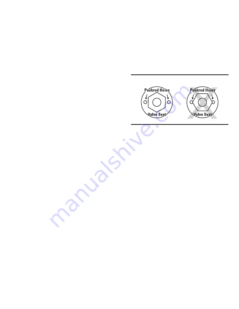
Caution:
Be sure hexagon corners of seat do not protrude into
pushrod holes (see Figure 10).
For valves that do not have replaceable elements or for Type O
valves, place the pushrod(s) into the body now.
8.
Next, slip the pin and carrier (which have been pressed
together at the factory) into the body and tap the pin into the
seat to form a true seating surface. It is generally advisable,
before tapping these parts together, to check the concentricity
of both the pin and seat by engaging the parts by pressing them
lightly together with one finger and noting that there is no
tendency to stick together. This should be repeated several
times after rotating the pin carrier a quarter of a turn. In
assembling valves with port sizes of 1/4" and larger which use
the flat disc instead of the tapered pin,
DO NOT TAP THE
DISC AGAINST THE SEAT.
9.
Now place the spring guide stamping (when used), and spring,
in the pin carrier, place the lower spring guide on the opposite
end of the spring and screw the bottom cap in place. (Replace
the pin guide, spring, and bottom cap assembly together on Type
(E)BF/SBF and EBS valves.) After screwing bottom cap
assembly in place, carefully tighten, preferable with two 10"
wrenches, to seal the metal-to-metal knife edge joint. The
sealing surfaces should be free of any foreign material or nicks
that might prevent a leak-tight joint.
10.
On valves with replaceable elements (except Types O,
(E)BF/SBF and EBS), place the pushrods into the body and
open the valve several times by pressing down on the pins with
a flat metal surface. This will help seat the pin properly.
11.
Check the height of the pushrod(s) above the element sealing
surface with the pushrod gauge (see Figure 11). The gauge is
supplied with internal parts kits or can be obtained at no charge
RIGHT
WRONG
Figure 10
Summary of Contents for VSM 71-701
Page 1: ...1 VPN 35391S February 2006 Rev 05 Price 60 00...
Page 2: ...2...
Page 20: ...20...
Page 52: ...53 Pre Start Up Check List...
Page 99: ...99 Recommended Spare Parts List...
Page 104: ...104 Gate Rotor...
Page 110: ...110 Main Rotor VSS...
Page 112: ...112 Main Rotor VSR...
Page 114: ...114 Slide Valve Cross Shafts and End Plate...
Page 118: ...118 Capacity Slide Volume Slide Carriage Assembly Slide Valve Carriage Assembly...
Page 134: ...134 Miscellaneous Frame Components VSS Screw Compressor VSR Mini Screw Compressor...
Page 138: ...138 C FlangeAdapter Components 630 620 610 640 601 641 630 601 620 610 640 641 642 650 651...
Page 140: ...140 Replacement Parts Tools...
Page 144: ...144 GaterotorAssembly...
Page 148: ...148 Main Rotor Slide Valve Cross Shafts and End Plate Models 71 401 Only Counter clockwise...
Page 152: ...152 Main Rotor Slide Valve Cross Shafts and End Plate Model 501 701 Only Clockwise...
Page 154: ...154 Volume Ratio Capacity Slide Carriage Assembly Slide Valve Carriage Assembly...
Page 158: ...158 Miscellaneous Frame Components Model VSM 501 701 Model VSM 71 401...
Page 160: ...160 Replacement Parts Accessories Housing Accessories C Flange Assembly...
Page 166: ...166 Haight Pumps...
Page 170: ...3 Refrigerating Specialties Division...
Page 236: ......
Page 237: ......
Page 238: ......
Page 243: ......
Page 244: ...168...


