43
Operation
I.
OIL SYSTEM
A.
Oil Charge
Charge the combination oil receiver/separator
with the proper quantity of lubricating oil (see
Installation Section).
CAUTION
It is imperative you charge the oil into the
receiver/separator prior to energizing the con-
trol panel to prevent burning out the immer-
sion heater in the separator/receiver.
During operation, maintain the receiver/sepa-
rator oil level in the normal operating range
between the two bullseye sight glasses. If the
oil level is visible only in the lowest sight glass,
add oil to the operating compressor through the
connection located at the compressor suction
inlet. Pump oil into the compressor until the
oil level in the separator is between the two
bullseye sight glasses. Watch this level care-
fully to maintain proper operation. Never al-
low the oil to reach a level higher than indi-
cated on the highest sight glass, since this may
impair the operation and efficiency of the oil
separator portion of this combination vessel.
B.
Oil Filter
Change the oil filter after the first 200 hours of
operation, as noted on the hour meter. There-
after, replace the filter every six months, or
when the oil pressure drop through the filter
reaches 45 psi, whichever occurs first. The
pressure drop across the filter is read on the
microprocessor panel. Check the pressure drop
and record it daily.
To prepare for the removal of the filter, shut
down the compressor. Isolate the filter housing
appropriate. If unit is equipped with duplex fil-
ter housings the unit does not have to be shut
down, however the filter to be serviced must be
isolated before the tank or bowl can be opened.
1.
Filter Removal and installation, all
VSR Units.
Release the pressure in the oil filter housing by
opening the bleed valves at the stop valve in
the block and bleed assembly, or at the bleed
valve for the oil filter housing. Be sure to fol-
low all Local, State and Federal ordinances re-
garding the recovery of refrigerants.
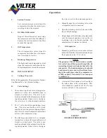
FIGURE 1.
TYPICAL CANISTER TYPE FILTER
CROSS SECTION
Drain the filter bowl or housing in to an appro-
priate container and dispose of the oil in a ap-
propriate manner following all Local, State and
Federal ordinances regarding the disposal of
used refrigeration oil.
Loosen and remove the locking ring on filter
tank by turning in a counter clockwise direc-
tion. Remove filter tank with the used element.
Remove the filter element from the tank. Be-
fore reassembling, thoroughly clean the tank
to lengthen the life span of the filter element.
Wet the threads and O-ring on the head and
the O-ring in the new element with clean re-
frigeration oil.
Summary of Contents for VSM 71-701
Page 1: ...1 VPN 35391S February 2006 Rev 05 Price 60 00...
Page 2: ...2...
Page 20: ...20...
Page 52: ...53 Pre Start Up Check List...
Page 99: ...99 Recommended Spare Parts List...
Page 104: ...104 Gate Rotor...
Page 110: ...110 Main Rotor VSS...
Page 112: ...112 Main Rotor VSR...
Page 114: ...114 Slide Valve Cross Shafts and End Plate...
Page 118: ...118 Capacity Slide Volume Slide Carriage Assembly Slide Valve Carriage Assembly...
Page 134: ...134 Miscellaneous Frame Components VSS Screw Compressor VSR Mini Screw Compressor...
Page 138: ...138 C FlangeAdapter Components 630 620 610 640 601 641 630 601 620 610 640 641 642 650 651...
Page 140: ...140 Replacement Parts Tools...
Page 144: ...144 GaterotorAssembly...
Page 148: ...148 Main Rotor Slide Valve Cross Shafts and End Plate Models 71 401 Only Counter clockwise...
Page 152: ...152 Main Rotor Slide Valve Cross Shafts and End Plate Model 501 701 Only Clockwise...
Page 154: ...154 Volume Ratio Capacity Slide Carriage Assembly Slide Valve Carriage Assembly...
Page 158: ...158 Miscellaneous Frame Components Model VSM 501 701 Model VSM 71 401...
Page 160: ...160 Replacement Parts Accessories Housing Accessories C Flange Assembly...
Page 166: ...166 Haight Pumps...
Page 170: ...3 Refrigerating Specialties Division...
Page 236: ......
Page 237: ......
Page 238: ......
Page 243: ......
Page 244: ...168...


