50
Operation
3.
Suction Pressure
Low suction pressure cutout stops the
compressor unit when the suction pres-
sure drops below the setpoint.
4.
Oil Filter Differential
High oil filter differential cutout stops
the compressor unit when the difference
between the outlet and inlet of the filter
exceeds the setpoint.
5.
Oil Temperature
The oil temperature cutout stops the
compressor unit when the oil tempera-
ture is too high or too low.
6.
Discharge Temperature
The high discharge temperature cutout
stops the compressor unit when the dis-
charge temperature exceeds the setpoint.
III.
INITIAL START-UP
A.
Setting of Controls
Refer to the appropriate Microprocessor Instruc-
tion Manual for a list of initial settings.
B.
Valve Settings
1.
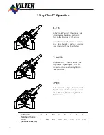
The suction stop/check valve is designed to
operate as a stop valve (manually open or
closed) or a check valve. The valve is nor-
mally positioned in the automatic mode dur-
ing unit operation. Please refer to the tag on
the valve to set it in the automatic position.
2.
The ¼” valve should be open during opera-
tion. The valve enables the unit to slowly
equalize to low side pressure during off peri-
ods. This valve must be adjusted to minimize
oil loss when compressor stops.
3.
The discharge stop/check valve is designed
to operate as a stop valve (manually open or
closed) or a check valve. The valve is nor-
mally positioned in the automatic mode dur-
ing unit operation. Please refer to the tag on
the valve to set it in the automatic position.
4.
Manually open the oil isolating valve at the
oil separator outlet connection.
5.
Open the isolating valve(s) before and after
the oil filter housings.
6.
On packages with a full time oil pump, make
sure the manual opening stem on the oil
regulating valve is in the auto position. See
manufacturer’s literature for details.
C.
Oil Separator
7.
Manually open the stop valve on the oil bleed
return line from the element section and open
the expansion valve 1/3 of a turn.
NOTE:
The purpose of the oil bleed return assembly
is to collect any oil that passes through the oil
separating element and returns that oil to the
compressor. The hand expansion valve should
be adjusted to prevent an oil level from form-
ing in the sight glass when the compressor is
at 100% capacity. Generally 1/3 to 1 turn open
is satisfactory.
8.
A second oil bleed return valve is located in
the mid section of the oil separator. This
valve should be opened about 1/2 of a turn
to meter oil back to the compressor.
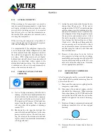
FIGURE 7.
OIL SEPARATOR BLEED LINE
Stop Valve
Summary of Contents for VSM 71-701
Page 1: ...1 VPN 35391S February 2006 Rev 05 Price 60 00...
Page 2: ...2...
Page 20: ...20...
Page 52: ...53 Pre Start Up Check List...
Page 99: ...99 Recommended Spare Parts List...
Page 104: ...104 Gate Rotor...
Page 110: ...110 Main Rotor VSS...
Page 112: ...112 Main Rotor VSR...
Page 114: ...114 Slide Valve Cross Shafts and End Plate...
Page 118: ...118 Capacity Slide Volume Slide Carriage Assembly Slide Valve Carriage Assembly...
Page 134: ...134 Miscellaneous Frame Components VSS Screw Compressor VSR Mini Screw Compressor...
Page 138: ...138 C FlangeAdapter Components 630 620 610 640 601 641 630 601 620 610 640 641 642 650 651...
Page 140: ...140 Replacement Parts Tools...
Page 144: ...144 GaterotorAssembly...
Page 148: ...148 Main Rotor Slide Valve Cross Shafts and End Plate Models 71 401 Only Counter clockwise...
Page 152: ...152 Main Rotor Slide Valve Cross Shafts and End Plate Model 501 701 Only Clockwise...
Page 154: ...154 Volume Ratio Capacity Slide Carriage Assembly Slide Valve Carriage Assembly...
Page 158: ...158 Miscellaneous Frame Components Model VSM 501 701 Model VSM 71 401...
Page 160: ...160 Replacement Parts Accessories Housing Accessories C Flange Assembly...
Page 166: ...166 Haight Pumps...
Page 170: ...3 Refrigerating Specialties Division...
Page 236: ......
Page 237: ......
Page 238: ......
Page 243: ......
Page 244: ...168...


