54
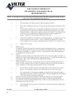
PRE START-UP CHECKLIST
FIELD PIPING AND MECHANICAL
REQUIREMENTS
NOTE:
If start-up service has been purchased, the following items should be completed before the start-up
man arrives. This will help save time and money.
_____
1.
The unit should be leveled and secured to the mounting pad or floor.
_____
2.
The suction and Discharge line must be piped and properly supported, independent of the
unit
_____
3.
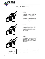
The Discharge Stop/Check Valve is shipped loose and must be installed in a vertical up f
low direction or in a horizontal line with the valve stem pointing upward at a 45° angle.
During off periods, refrigerant can condense in the line downstream of the Discharge Stop/
Check Valve. It is recommended the Stop/Check Valve be located to minimize the
quantity of liquid that can accumulate downstream of the valve.
_____
4.
A Dual Safety Relief Valve is shipped loose for field installation. A connection is provided
on the oil separator for the relief valve. Refer to ASHRAE/ANSI Standard 15 (Safety
Code for Refrigeration) for proper sizing and installation of Relief Valves and Vent Lines.
_____
5.
Piping For Oil Cooling
a)
Liquid Injection
An adequate, or dedicated, liquid line is required for the Liquid Injection System. A high pressure
liquid source must be piped to the stop valve at the inlet of the Thermostatic Expansion Valve. On
booster units, an additional
3
/
8
” line must be piped to the regulator from high stage discharge gas f
or the Thermostatic Expansion Valve.
b)
V-PLUS
A high pressure liquid source must be run to the V-PLUS
®
inlet. Some subcooling is desirable. A
high pressure float must be installed at the inlet of the pump and a
3
/
8
” vent line must be returned to
a suction trap. Refer to the V-PLUS manual for additional information.
c)
External Oil Cooler
On thermosyphon oil coolers, the refrigerant lines must be connected to the front head of the oil
cooler. On water cooled oil coolers, the water lines must be connected to the front head of the oil
cooler. Installation of water regulating and solenoid valves are recommended.
_____
6.
The oil separator should be provided with oil until the oil level is between the (2) sight
glasses. An oil charging connection is provided on the bottom of the oil separator.
_____
7.
The center member of the compressor coupling is shipped loose to help facilitate final f
ield alignment and allow for motor rotation check. The motor alignment should be within
0.004” total indicator reading in all directions.
a)
Both the compressor and motor hubs should be checked for concentricity and perpendicularity.
b)
The motor should be checked and shimmed for soft foot prior to attempting final alignment.
c)
The center section of the coupling should be left out to allow the start-up technician to verify the
final alignment and motor rotations.
_____
8.
The unit should be pressure tested, evacuated and a system load should be available at the
time of start-up.
Order #_______________________________Compressor Serial #________________________
Summary of Contents for VSM 71-701
Page 1: ...1 VPN 35391S February 2006 Rev 05 Price 60 00...
Page 2: ...2...
Page 20: ...20...
Page 52: ...53 Pre Start Up Check List...
Page 99: ...99 Recommended Spare Parts List...
Page 104: ...104 Gate Rotor...
Page 110: ...110 Main Rotor VSS...
Page 112: ...112 Main Rotor VSR...
Page 114: ...114 Slide Valve Cross Shafts and End Plate...
Page 118: ...118 Capacity Slide Volume Slide Carriage Assembly Slide Valve Carriage Assembly...
Page 134: ...134 Miscellaneous Frame Components VSS Screw Compressor VSR Mini Screw Compressor...
Page 138: ...138 C FlangeAdapter Components 630 620 610 640 601 641 630 601 620 610 640 641 642 650 651...
Page 140: ...140 Replacement Parts Tools...
Page 144: ...144 GaterotorAssembly...
Page 148: ...148 Main Rotor Slide Valve Cross Shafts and End Plate Models 71 401 Only Counter clockwise...
Page 152: ...152 Main Rotor Slide Valve Cross Shafts and End Plate Model 501 701 Only Clockwise...
Page 154: ...154 Volume Ratio Capacity Slide Carriage Assembly Slide Valve Carriage Assembly...
Page 158: ...158 Miscellaneous Frame Components Model VSM 501 701 Model VSM 71 401...
Page 160: ...160 Replacement Parts Accessories Housing Accessories C Flange Assembly...
Page 166: ...166 Haight Pumps...
Page 170: ...3 Refrigerating Specialties Division...
Page 236: ......
Page 237: ......
Page 238: ......
Page 243: ......
Page 244: ...168...


