60
Service
0.05
ANNUAL INSPECTION
The Vilter Single Screw Compressor is designed
for long periods of trouble free operation with a
minimum of maintenance. However, a yearly in-
spection is recommended so any irregular wear is
noted and rectified. At this time, the bearing float
is measured for the main rotor and gate rotors.
The following are the procedures used in measur-
ing the main rotor and gate rotor bearing float.
CAUTION
When taking the measurements, do not exceed
300 to 500 Lbs. of force at point of contact or
damage may result to the bearings.
A) Shut down and de-pressurize the unit, as
outlined in section 0.01.
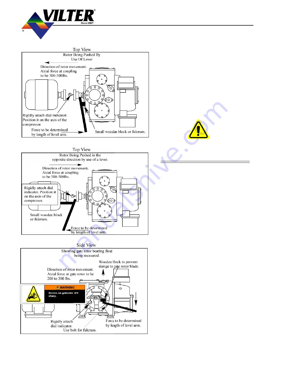
B) Main rotor bearing float.
1)
Remove the coupling guard, then re-
move the center member from the cou-
pling.
2)
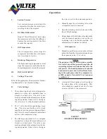
Attach a dial indicator to the compres-
sor frame as shown and zero indicator.
Place a lever arm and fulcrum behind
the compressor coupling half and push
the coupling towards the motor (note
measurement).
TABLE 0.1MAXIMUM BEARING FLOAT
MAIN GATE
Bearing Float
0.003” 0.002”
Maximum Force
300 to 500 200 to 300
Lbs. Lbs.
3)
Re-Zero indicator, now position the ful-
crum on the motor and use the lever arm
to push the input shaft towards the com-
pressor (note measurement).
4)
Add both readings, the total indicator
movement is the bearing float and this
should not exceed 0.003”.
Summary of Contents for VSM 71-701
Page 1: ...1 VPN 35391S February 2006 Rev 05 Price 60 00...
Page 2: ...2...
Page 20: ...20...
Page 52: ...53 Pre Start Up Check List...
Page 99: ...99 Recommended Spare Parts List...
Page 104: ...104 Gate Rotor...
Page 110: ...110 Main Rotor VSS...
Page 112: ...112 Main Rotor VSR...
Page 114: ...114 Slide Valve Cross Shafts and End Plate...
Page 118: ...118 Capacity Slide Volume Slide Carriage Assembly Slide Valve Carriage Assembly...
Page 134: ...134 Miscellaneous Frame Components VSS Screw Compressor VSR Mini Screw Compressor...
Page 138: ...138 C FlangeAdapter Components 630 620 610 640 601 641 630 601 620 610 640 641 642 650 651...
Page 140: ...140 Replacement Parts Tools...
Page 144: ...144 GaterotorAssembly...
Page 148: ...148 Main Rotor Slide Valve Cross Shafts and End Plate Models 71 401 Only Counter clockwise...
Page 152: ...152 Main Rotor Slide Valve Cross Shafts and End Plate Model 501 701 Only Clockwise...
Page 154: ...154 Volume Ratio Capacity Slide Carriage Assembly Slide Valve Carriage Assembly...
Page 158: ...158 Miscellaneous Frame Components Model VSM 501 701 Model VSM 71 401...
Page 160: ...160 Replacement Parts Accessories Housing Accessories C Flange Assembly...
Page 166: ...166 Haight Pumps...
Page 170: ...3 Refrigerating Specialties Division...
Page 236: ......
Page 237: ......
Page 238: ......
Page 243: ......
Page 244: ...168...


