61
Service
C)
Gate rotor bearing float.
1)
Remove the side covers and position a
dial indicator on the gate rotor.
2)
Use a lever arm pivoting on a bolt with a
small block of wood against the gate ro-
tor blade to protect the blade.
3)
The maximum amount of bearing float
should not exceed 0.002”.
D) Measure the gate rotor to blade float. Some
movement between blade and support is nec-
essary to prevent damage to the compressor
blade, however at no time should the blade
uncover the support.
1)
Position the blade with the gate rotor
damper pin and 90º to the main rotor.
2)
Position a dial indicator at the tip of the
support. The total movement of the
damper pin in the bushing is the gate
rotor float. Refer to table 0.2 to find the
maximum blade to support float (on new
compressor parts only).
TABLE 0.2.
GATE ROTOR FLOAT
MODEL
FLOAT
VSM 71 THRU 401
0.045”
VSM 501 THRU 701
0.045”
VSR 111 THRU VSS 601
0.045”
VSS 751 & VSS 901
0.055”
VSS 1051 & VSS 1201
0.060”
VSS 1501 & VSS 1801
0.060”
E)
Readings could be higher than 0.020. If
readings is greater than 0.030 over table
tolerance contact Vilter’s home office.
F)
Inspect the main and gate rotors for
signs of abnormal wear due to dirt or
other contaminants.
G)
After the inspection is complete, the
covers, coupling center member and
guard can be reinstalled and the unit can
then be evacuated and leak checked be-
fore starting.
0.06
NORD-LOCK WASHERS
A) Nord-Lock
®
lock washer sets are used in
many areas on the Single Screw Compres-
sor that requires a vibration proof lock
washer.
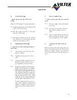
B) The lock washer set is assembled so the
course serrations that resemble ramps are
mated together.
C)
Once the lock washer set is tightened down,
it takes more force to loosen the bolt then it
did to tighten it. This is caused by the wash-
ers riding up the opposing serrations.
r
a
m
p
.
Fine serrations face out.
Coarse serrations
mate together.
Coarse Serrations
mate together
Summary of Contents for VSM 71-701
Page 1: ...1 VPN 35391S February 2006 Rev 05 Price 60 00...
Page 2: ...2...
Page 20: ...20...
Page 52: ...53 Pre Start Up Check List...
Page 99: ...99 Recommended Spare Parts List...
Page 104: ...104 Gate Rotor...
Page 110: ...110 Main Rotor VSS...
Page 112: ...112 Main Rotor VSR...
Page 114: ...114 Slide Valve Cross Shafts and End Plate...
Page 118: ...118 Capacity Slide Volume Slide Carriage Assembly Slide Valve Carriage Assembly...
Page 134: ...134 Miscellaneous Frame Components VSS Screw Compressor VSR Mini Screw Compressor...
Page 138: ...138 C FlangeAdapter Components 630 620 610 640 601 641 630 601 620 610 640 641 642 650 651...
Page 140: ...140 Replacement Parts Tools...
Page 144: ...144 GaterotorAssembly...
Page 148: ...148 Main Rotor Slide Valve Cross Shafts and End Plate Models 71 401 Only Counter clockwise...
Page 152: ...152 Main Rotor Slide Valve Cross Shafts and End Plate Model 501 701 Only Clockwise...
Page 154: ...154 Volume Ratio Capacity Slide Carriage Assembly Slide Valve Carriage Assembly...
Page 158: ...158 Miscellaneous Frame Components Model VSM 501 701 Model VSM 71 401...
Page 160: ...160 Replacement Parts Accessories Housing Accessories C Flange Assembly...
Page 166: ...166 Haight Pumps...
Page 170: ...3 Refrigerating Specialties Division...
Page 236: ......
Page 237: ......
Page 238: ......
Page 243: ......
Page 244: ...168...

