77
Service
shafts and the slide valve racks as outlined in
section 4.10.
D) Locate and remove the socket head plugs
above the slide valve carriage attachment
bolts. Remove the bolts located under the
plugs.
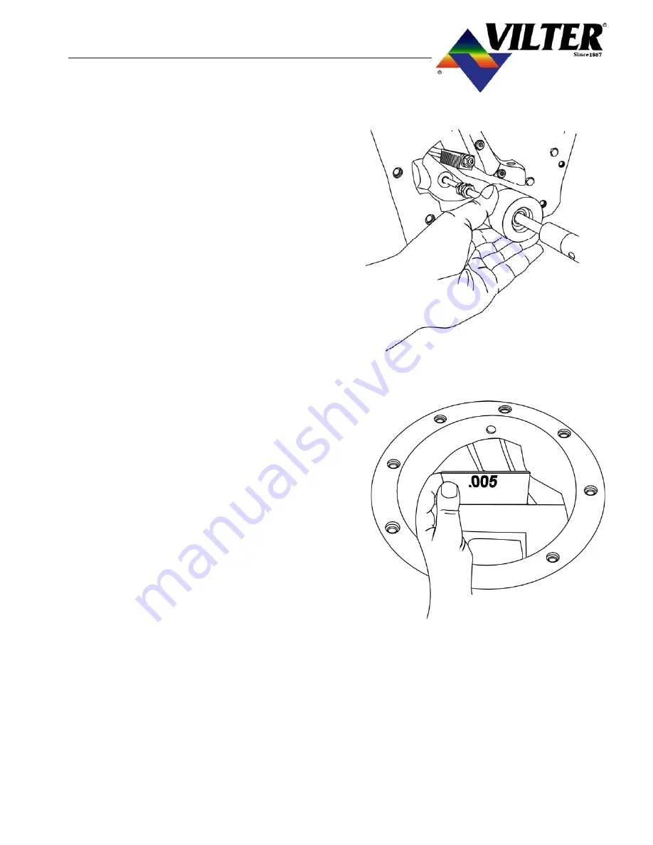
E) The slide valve carriage may now be re-
moved. On newer carriages there is a
threaded hole in the back of the slide valve
carriage to aid in its removal. Use a threaded
tip slide hammer to aid in the removal of the
carriage.
Note: Slide Valves may be re-positioned to aid
in removal of assembly.
3.20
INSTALLATION OF SLIDE
VALVE CARRIAGE ASSEMBLIES
A) Position the slide valves to the center of the
carriage. Place the slide valve assembly in
the bore of frame and use the slide hammer
to slowly tap the carriage into position. Re-
positioning slide valves once inside bore may
aid installation. Adjust the carriage so that
the 3-holes line up.
B) Install the 3 socket head cap screws with new
Nord-Lock washers beneath the heads, but
do not tighten them.
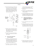
C) Work a piece of 0.005”shim stock between
the slide valves and the main rotor to help
position the carriage.
D) Tighten, to the correct torque the hold down
bolts to secure the carriage in the frame. The
edges of the slide valves themselves should
be at or slightly below the main rotor bore.
E) Re- Install the capacity and volume slide
valve cross shafts, slide valve racks and dis-
charge manifold as outlined in section 4.01.
F)
Re-install the gate rotor assemblies as out-
lined in section 1.02
Summary of Contents for VSM 71-701
Page 1: ...1 VPN 35391S February 2006 Rev 05 Price 60 00...
Page 2: ...2...
Page 20: ...20...
Page 52: ...53 Pre Start Up Check List...
Page 99: ...99 Recommended Spare Parts List...
Page 104: ...104 Gate Rotor...
Page 110: ...110 Main Rotor VSS...
Page 112: ...112 Main Rotor VSR...
Page 114: ...114 Slide Valve Cross Shafts and End Plate...
Page 118: ...118 Capacity Slide Volume Slide Carriage Assembly Slide Valve Carriage Assembly...
Page 134: ...134 Miscellaneous Frame Components VSS Screw Compressor VSR Mini Screw Compressor...
Page 138: ...138 C FlangeAdapter Components 630 620 610 640 601 641 630 601 620 610 640 641 642 650 651...
Page 140: ...140 Replacement Parts Tools...
Page 144: ...144 GaterotorAssembly...
Page 148: ...148 Main Rotor Slide Valve Cross Shafts and End Plate Models 71 401 Only Counter clockwise...
Page 152: ...152 Main Rotor Slide Valve Cross Shafts and End Plate Model 501 701 Only Clockwise...
Page 154: ...154 Volume Ratio Capacity Slide Carriage Assembly Slide Valve Carriage Assembly...
Page 158: ...158 Miscellaneous Frame Components Model VSM 501 701 Model VSM 71 401...
Page 160: ...160 Replacement Parts Accessories Housing Accessories C Flange Assembly...
Page 166: ...166 Haight Pumps...
Page 170: ...3 Refrigerating Specialties Division...
Page 236: ......
Page 237: ......
Page 238: ......
Page 243: ......
Page 244: ...168...


