81
Service
457 477
415
C)
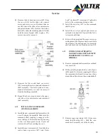
Remove four socket head cap screws (457)
and Nord-Lock washers (477) securing
mounting plate (415) to manifold.
D) The command shaft and mounting plate may
now be removed from the compressor.
4.06
COMMAND SHAFT ASSEMBLY
INSTALLATION
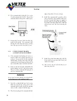
A) Install the command shaft assembly with a
new o-ring (446) on the manifold. Make sure
that the command shaft tongue is engaged
in the cross shaft slot. Rotate the bearing
housing so the vent holes point down, this
will prevent water and dust from entering
the vents.
Command shaft
assembly.
Align the tongue of
the command shaft
with the groove in the
cross shaft.
446
Rotate bearing housing
so vent hole points down.
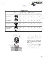
B) Install the actuator mounting plate with the
four socket head cap screws and Nord-Lock
washers securing it with proper torque.
C)
The unit can now be leak checked as out-
lined in section 0.03.]
4.07
COMMAND SHAFT BEARING
AND O-RING SEAL
REPLACEMENT
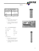
A) Remove command shaft assembly as outlined
in section 4.05.
B)
Remove snap ring retainer (451) from com-
mand shaft housing (412). Push the com-
mand shaft assembly out of the housing.
C)
The command shaft bearing (435) is a press
fit on the command shaft (413). Remove the
command shaft bearing with a suitable press.
436
445
Vent hole.
D) Remove the O-ring seal (445) from the com-
mand shaft housing. The command shaft
bushing (433 and 436) might have to be re-
moved to gain access to o-rings. Replace
bushing if the bore is deeply scored or exces-
sively worn.
Old Style Motor Plate
Div.2
O n l y
Reference “Parts
Section” for current
H o u s i n g
Summary of Contents for VSM 71-701
Page 1: ...1 VPN 35391S February 2006 Rev 05 Price 60 00...
Page 2: ...2...
Page 20: ...20...
Page 52: ...53 Pre Start Up Check List...
Page 99: ...99 Recommended Spare Parts List...
Page 104: ...104 Gate Rotor...
Page 110: ...110 Main Rotor VSS...
Page 112: ...112 Main Rotor VSR...
Page 114: ...114 Slide Valve Cross Shafts and End Plate...
Page 118: ...118 Capacity Slide Volume Slide Carriage Assembly Slide Valve Carriage Assembly...
Page 134: ...134 Miscellaneous Frame Components VSS Screw Compressor VSR Mini Screw Compressor...
Page 138: ...138 C FlangeAdapter Components 630 620 610 640 601 641 630 601 620 610 640 641 642 650 651...
Page 140: ...140 Replacement Parts Tools...
Page 144: ...144 GaterotorAssembly...
Page 148: ...148 Main Rotor Slide Valve Cross Shafts and End Plate Models 71 401 Only Counter clockwise...
Page 152: ...152 Main Rotor Slide Valve Cross Shafts and End Plate Model 501 701 Only Clockwise...
Page 154: ...154 Volume Ratio Capacity Slide Carriage Assembly Slide Valve Carriage Assembly...
Page 158: ...158 Miscellaneous Frame Components Model VSM 501 701 Model VSM 71 401...
Page 160: ...160 Replacement Parts Accessories Housing Accessories C Flange Assembly...
Page 166: ...166 Haight Pumps...
Page 170: ...3 Refrigerating Specialties Division...
Page 236: ......
Page 237: ......
Page 238: ......
Page 243: ......
Page 244: ...168...


