82
Service
4.08
COMMAND SHAFT BEARING
AND O-RING SEAL
REASSEMBLY
A) Install new O-ring seal in housing and lu-
bricate the O-ring with clean compressor oil.
A vent hole is provided in the command shaft
bearing housing to allow any refrigerant and
oil that may leak past the O-ring seal to vent
to atmosphere and not into the slide valve
motor housing. Install snap ring retainer and
washer on the command shaft.
B) Remove any burrs from the command shaft
to prevent damage to the O-ring when as-
sembling. Press the command shaft bearing
onto the command shaft. Insert the com-
mand shaft into the housing appling pres-
sure on outer race of bearing. Make sure the
bearing is fully seated in the command shaft
housing. Install the snap ring retainer in
the command shaft housing.
C) Install command shaft assembly as outlined
in section 4.02.
4.09
DISCHARGE MANIFOLD
REMOVAL
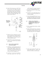
A) Remove both control actuators and command
shaft assemblies as outlined in sections 4.01
and 4.05.
B) On VSS and VSR compressors, remove the
discharge spool between the manifold and
separator. Remove one bolt from each side
of the discharge manifold and install (2)
guide rods approximately 6” long, to sup-
port the manifold. Remove the remaining
bolts (note length and location of bolts) and
take off the discharge manifold.
Note: Mainfold has dowel pins to locate it
on the compressor housing. Therefore, re-
move manifold straight back approximately
1” as not to break dowel pins.
547
548
549
550
551
540
536
512
511
519
Guide rods
Discharge
spool
NOTE:
When removing the discharge manifold on VSM
compressor the compressor must be properly sup-
ported to keep the compressor from moving when
the manifold is removed.
C) On VSM compressors unbolt the discharge
flange from the discharge manifold.
D) Remove one bolt from each side of the dis-
charge manifold and install (2) guide rods
approximately 6” long, to support the mani-
fold. Remove the remaining bolts (note
length and location of bolts) and take off the
discharge manifold.
4.10
DISCHARGE MANIFOLD
INSTALLATION
A) Install (2) guide rods to position the dis-
charge manifold. Install a new manifold
gasket and the discharge manifold. Install
the dowel pins and bolts, tighten manifold
bolts to the recommended torque value.
B) On VSS and VSR compressors install the
discharge spool or elbow between the dis-
charge manifold and oil separator with new
gaskets. When installing the discharge el-
bow tighten the bolts to the correct torque
on the manifold flange first before tighten-
ing the separator flange bolts. Install the
drain plug in the bottom of the discharge
manifold.
Summary of Contents for VSM 71-701
Page 1: ...1 VPN 35391S February 2006 Rev 05 Price 60 00...
Page 2: ...2...
Page 20: ...20...
Page 52: ...53 Pre Start Up Check List...
Page 99: ...99 Recommended Spare Parts List...
Page 104: ...104 Gate Rotor...
Page 110: ...110 Main Rotor VSS...
Page 112: ...112 Main Rotor VSR...
Page 114: ...114 Slide Valve Cross Shafts and End Plate...
Page 118: ...118 Capacity Slide Volume Slide Carriage Assembly Slide Valve Carriage Assembly...
Page 134: ...134 Miscellaneous Frame Components VSS Screw Compressor VSR Mini Screw Compressor...
Page 138: ...138 C FlangeAdapter Components 630 620 610 640 601 641 630 601 620 610 640 641 642 650 651...
Page 140: ...140 Replacement Parts Tools...
Page 144: ...144 GaterotorAssembly...
Page 148: ...148 Main Rotor Slide Valve Cross Shafts and End Plate Models 71 401 Only Counter clockwise...
Page 152: ...152 Main Rotor Slide Valve Cross Shafts and End Plate Model 501 701 Only Clockwise...
Page 154: ...154 Volume Ratio Capacity Slide Carriage Assembly Slide Valve Carriage Assembly...
Page 158: ...158 Miscellaneous Frame Components Model VSM 501 701 Model VSM 71 401...
Page 160: ...160 Replacement Parts Accessories Housing Accessories C Flange Assembly...
Page 166: ...166 Haight Pumps...
Page 170: ...3 Refrigerating Specialties Division...
Page 236: ......
Page 237: ......
Page 238: ......
Page 243: ......
Page 244: ...168...


