83
Service
C)
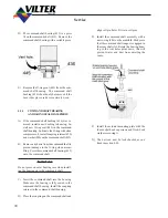
On VSM compressors install the bolts in the
discharge flange. Install the drain plug in
the bottom of the discharge manifold.
D) Install both command shaft assemblies and
control actuators as outlined in sections 4.05
and 4.01.
4.11
SLIDE VALVE GEAR AND RACK
INSPECTION
A) Remove the discharge manifold as outlined
in section 4.09
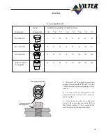
B) Check rack to rack clamp and rack clamp
spacer clearance on all four slide valves.
TABLE 4.1
RACK CLEARANCE VALUES
MEASUREMENT
CLEARANCE
Rack to clamp.
0.005 to 0.010”
Rack to clamp spacer.
0.003 to 0.005”
C) Check torque of socket heat cap screws.
D) Check for excessive movement between the
slide valve rack shafts and the rack. The
jam nuts on the end of the slide valve rack
shaft should be tight.
E) Check for loose or broken roll pins in gears.
Loose nuts
Roll pins
Rack to
clamp
Rack to
spacer
clamp
Check
on cap
torque
screws
F)
Look for any excessive wear on all moving
parts and replace the worn parts.
G)
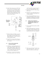
Reassemble the manifold and discharge el-
bow as outlined in section 4.10.
4.12
REMOVAL OF CAPACITY OR
VOLUME CROSS SHAFTS
A) Remove the discharge manifold as outlined
in section 4.09.
B)
To remove the capacity or volume ratio slide
valve racks, remove the two jam nuts and lock
washers (361) securing the rack (316) to the
slide valve shafts. The racks can now be
pulled off the slide valve shafts. Repeat the
procedure for the remaining pair of slide valve
racks.
C)
To remove the cross shafts, remove socket
head bolts, clamp and spacers from both
sides.
Summary of Contents for VSM 71-701
Page 1: ...1 VPN 35391S February 2006 Rev 05 Price 60 00...
Page 2: ...2...
Page 20: ...20...
Page 52: ...53 Pre Start Up Check List...
Page 99: ...99 Recommended Spare Parts List...
Page 104: ...104 Gate Rotor...
Page 110: ...110 Main Rotor VSS...
Page 112: ...112 Main Rotor VSR...
Page 114: ...114 Slide Valve Cross Shafts and End Plate...
Page 118: ...118 Capacity Slide Volume Slide Carriage Assembly Slide Valve Carriage Assembly...
Page 134: ...134 Miscellaneous Frame Components VSS Screw Compressor VSR Mini Screw Compressor...
Page 138: ...138 C FlangeAdapter Components 630 620 610 640 601 641 630 601 620 610 640 641 642 650 651...
Page 140: ...140 Replacement Parts Tools...
Page 144: ...144 GaterotorAssembly...
Page 148: ...148 Main Rotor Slide Valve Cross Shafts and End Plate Models 71 401 Only Counter clockwise...
Page 152: ...152 Main Rotor Slide Valve Cross Shafts and End Plate Model 501 701 Only Clockwise...
Page 154: ...154 Volume Ratio Capacity Slide Carriage Assembly Slide Valve Carriage Assembly...
Page 158: ...158 Miscellaneous Frame Components Model VSM 501 701 Model VSM 71 401...
Page 160: ...160 Replacement Parts Accessories Housing Accessories C Flange Assembly...
Page 166: ...166 Haight Pumps...
Page 170: ...3 Refrigerating Specialties Division...
Page 236: ......
Page 237: ......
Page 238: ......
Page 243: ......
Page 244: ...168...


