65
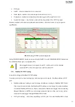
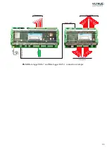
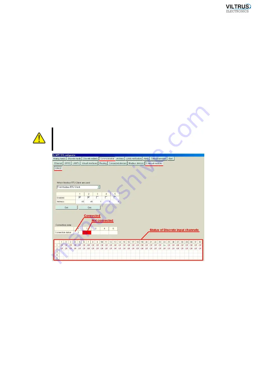
indication) can be used as Alarms. If connection to Master data logger is established over Modbus
TCP/IP (Ethernet or GPRS), then in table, at the bottom of page, you will see statys of each
Discrete input (because of slow connection in Modbus RTU mode table will be invisible).
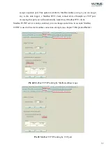
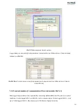
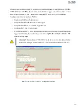
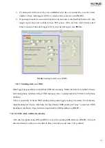
To setup connection you need (see
•
Equal setup UARTs on bouth devices;
•
Setup Modbus RTU client on master
d
ata logger;
•
Setup Modbus RTU server on
D
ata logger RAY-1;
•
Configure RAY-1 as External mode;
•
If to
D
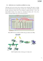
ata logger RAY-1 with configuration program you will connect through Master
d
ata
logger (not directly), then additionaly you need to setup Modbus TCP_IP to Modbus RTU
address routing range.
Attention!:
Basic address of “VILTRUS” made devices is two last digits of serial
number (for example, if serial number is 77715, then default address will be 15).
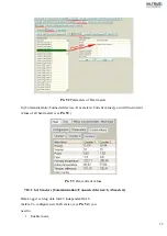
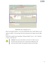
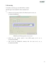
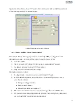
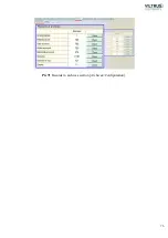
Pic 59
External device RAY-1 configuration screen
Summary of Contents for MX-7
Page 1: ...2 ...
Page 4: ...5 9 6 USB cable 85 9 7 Installing VILTRUS USB driver 85 9 8 TCP IP settings 87 ...
Page 22: ...23 see Pic 6 3 6 V 5 V 6V 8 V 10 V Pic 6 Power for external device DIP switch ...
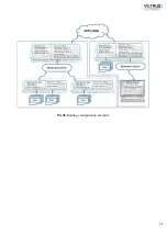
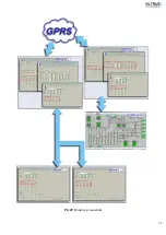
Page 53: ...54 Pic 48 Routing configuration example ...
Page 54: ...55 Pic 49 Routing screenshots ...
Page 59: ...60 2 Set COM port number UART port must be configured and assigned to COM client on ...
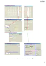
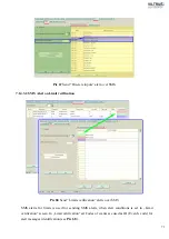
Page 66: ...67 Pic 61 Setting up RAY 1 as External module by example ...
Page 75: ...76 Pic 71 Records in archives section Archives Configutation ...

