21
5. INSTALLATION
5.1
Mounting device
The device is prepared for mounting on DIN rail. Loosen the screws on both sides of data logger’s
encloser. First hang on the rail the top part of encloser, then gently pressing down evenly push
the device to the DIN rail and tightly vice locking screws on both sides of device.
5.2
Connecting
Before starting be sure, that data logger and all peripherical devices, that you are
going to connect over serial interfaces (RS232, RS485, Current loop, Data/Req,
M-Bus and etc.), Discrete IN, Discrete OUT and Analog IN channels are switched
off.
Connecting the polarity-sensitive interfaces – carefully follow the notations on contacts.
If you are connecting interfaces, that use separate channels for data transmission (TX) and
reception (RX) – switch them, that TX from one device has go to RX from another, and RX to
TX. If you connect TX to TX and RX to RX – data will not be sent and received through these
interfaces.
First turn ON the power on peripherical devices, and only when they boots-up – turn ON data
logger’s power.
5.3
Switching
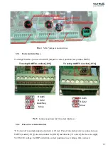
Devices has special interfaces which using jumpers can be switched between few prepared
interfaces – we call them Universal (it’s an optional interfaces see “Manufacturer’s code” and
explanation on chapter
3.2
to find if your device supports Universal interfaces
)
.
And some devices have Power for external devices – we call them “U Corrector” (it’s an optional
enhancement see “Manufacturer’s code” and explanation on chapter
3.2
to find if your device
supports U Corrector
)
.
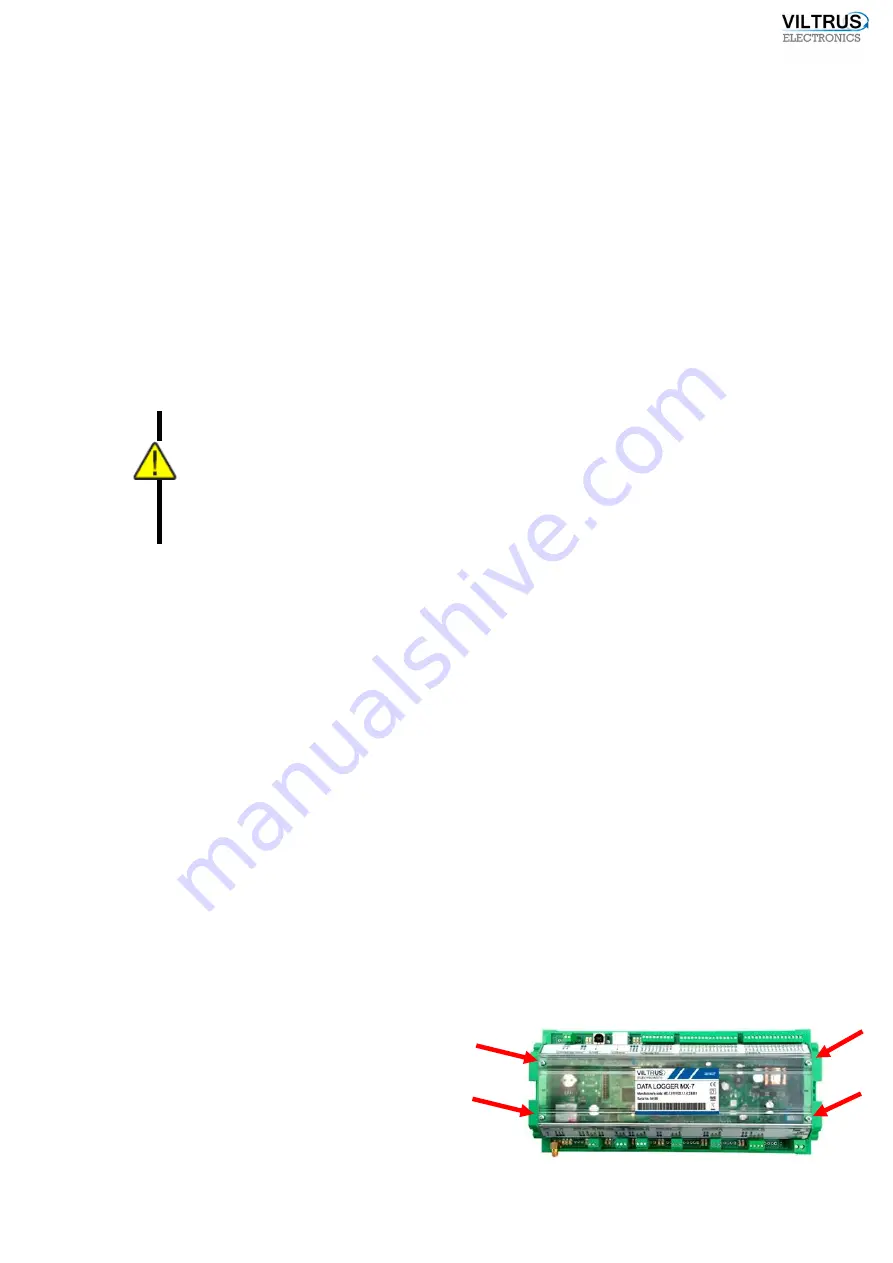
To find installed switches, unscrew 4 skews, that
are keeping transparent front cover and take it
to find installed switches on your
data logger easier,
Summary of Contents for MX-7
Page 1: ...2 ...
Page 4: ...5 9 6 USB cable 85 9 7 Installing VILTRUS USB driver 85 9 8 TCP IP settings 87 ...
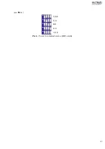
Page 22: ...23 see Pic 6 3 6 V 5 V 6V 8 V 10 V Pic 6 Power for external device DIP switch ...
Page 53: ...54 Pic 48 Routing configuration example ...
Page 54: ...55 Pic 49 Routing screenshots ...
Page 59: ...60 2 Set COM port number UART port must be configured and assigned to COM client on ...
Page 66: ...67 Pic 61 Setting up RAY 1 as External module by example ...
Page 75: ...76 Pic 71 Records in archives section Archives Configutation ...


