39
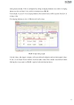
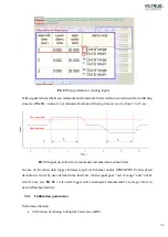
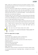
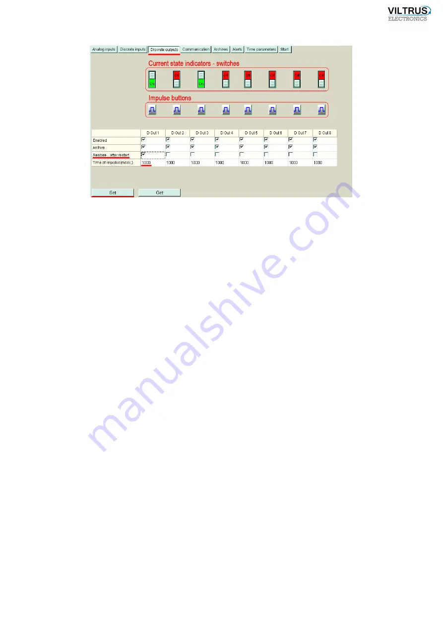
Pic 28
Discrete outputs usage [Discrete outputs]
By using check box you can Enable/Disable each Discrete Out channel and changed status
archiving. If you need to have last Discrete Out channel stage, even after restarting or power off
– select “Restore after restart” (for example see Pic 28 , “D Out 1” channel), then last stage will
be saved in energy independent memory and restored after restart.
Data logger can make user-defined duration control impulse. In section “Time of impuse” set
duration, value can be from 100 to 20 000 msec., (see Pic 28 ).
If some parameters was changed - press “Set”, to send data to data logger.
7.5
USB (device)
USB (device) interface is not listed in Manufacturer’s code, but is installed by default. This
interface is used for local configuration (how to connect to data logger, using USB (device), see
chapter
6.4
).
7.6
Ethernet
Ethernet interface is used for:
•
d
ata logger setup;
•
data transferring to central computer;
•
firmware upgrade.
Supported protocols:
•
Modbus TCP/IP Server – for data transfer;
•
Modbus TCP/IP Client – for events alert;
Summary of Contents for MX-7
Page 1: ...2 ...
Page 4: ...5 9 6 USB cable 85 9 7 Installing VILTRUS USB driver 85 9 8 TCP IP settings 87 ...
Page 22: ...23 see Pic 6 3 6 V 5 V 6V 8 V 10 V Pic 6 Power for external device DIP switch ...
Page 53: ...54 Pic 48 Routing configuration example ...
Page 54: ...55 Pic 49 Routing screenshots ...
Page 59: ...60 2 Set COM port number UART port must be configured and assigned to COM client on ...
Page 66: ...67 Pic 61 Setting up RAY 1 as External module by example ...
Page 75: ...76 Pic 71 Records in archives section Archives Configutation ...

