7
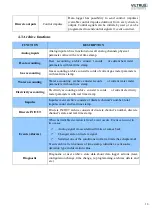
protocols used for connection, communication and power supply between computer and electronic
devices. USB type B socket is prepared for connection to PC (Personal Computer). USB type A
socket is prepared for connection to peripheral devices (example memory stick’s and etc.).
M-Bus -
a European standard (EN 13757-2 physical and link layer, EN 13757-3 application layer)
for the remote reading of gas or electricity meters. The M-Bus interface is made for
communication on two wire, making it very cost effective.
MBUS+ –
contact for M-Bus positive wire
MBUS- –
contact for M-Bus negative wire
Socket
– is an endpoint of a bidirectional inter-process communication flow across an Internet
Protocol-based computer network, such as the Internet
Data/Req –
are protocol used by Kamstrup, for data transfer over two wires are
Data –
contact for data wire
Req –
contact for request wire
Current loop -
are used where a device must be monitored or controlled remotely over a pair of
conductors. Only one current level can be present at any time.
CL+ –
contact for current loop positive wire
CL
-
–
contact for current loop negative wire
1.2
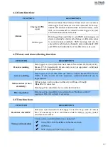
LED indications
Status –
device status indicating LED
Output –
status of power for external device indicating LED
TX/RX –
data transfer/receive indicating LED
TXD –
data transferring LED indicator
RXD –
data receiving LED indicator
100Mbs –
Ethernet High speed connection indicating LED
1.3
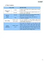
Explanations
“Alarm mode” –
in state of alarm status Data Logger initiates an event notification for user
selected discrete input mode (Alarm mode: unconnected, connected, both events)
Central computer –
server or a computer, where data can be sent.
IP
address - An
Internet Protocol
(
IP
)
address
is a numerical label that is assigned to devices
participating in a network that uses the Internet Protocol for communication between its nodes.
TCP/IP
– Transmission Control Protocol is for communication between computers, used as a
Summary of Contents for MX-7
Page 1: ...2 ...
Page 4: ...5 9 6 USB cable 85 9 7 Installing VILTRUS USB driver 85 9 8 TCP IP settings 87 ...
Page 22: ...23 see Pic 6 3 6 V 5 V 6V 8 V 10 V Pic 6 Power for external device DIP switch ...
Page 53: ...54 Pic 48 Routing configuration example ...
Page 54: ...55 Pic 49 Routing screenshots ...
Page 59: ...60 2 Set COM port number UART port must be configured and assigned to COM client on ...
Page 66: ...67 Pic 61 Setting up RAY 1 as External module by example ...
Page 75: ...76 Pic 71 Records in archives section Archives Configutation ...


