9
2. PREFACE
2.1
Symbols
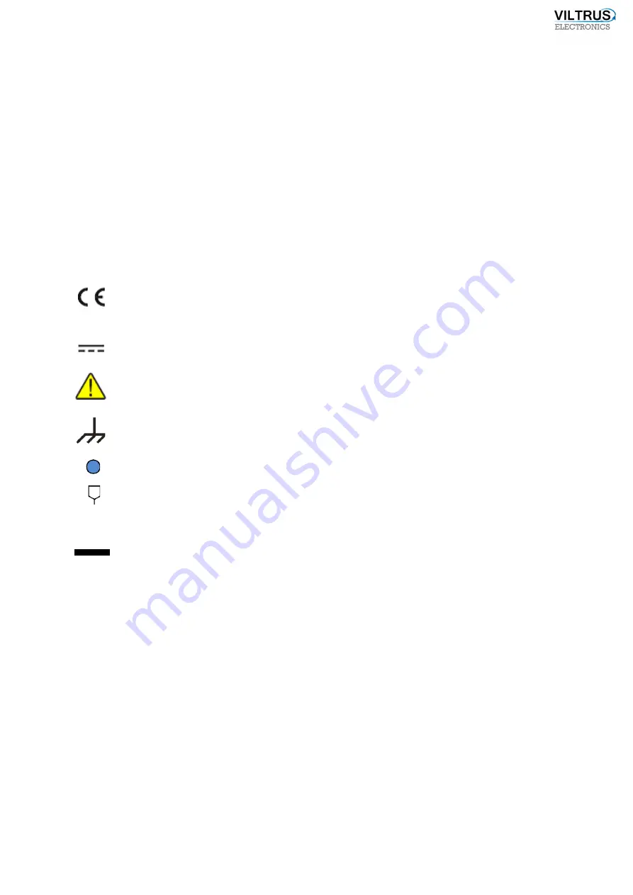
International electrical symbol list. Some or all symbols can be used on data logger marking or
in this user manual.
Symbol
Explanation
With the
CE
marking on a product the manufacturer ensures that the
product conforms with the essential requirements of the applicable
EC
directives.
DC
(Direct Current)
Caution
Grounding
LED indicator
1
Contact number on plug
RoHS
Directive on the restriction of the use of certain hazardous substances in
electrical and electronic equipment 2002/95/EC. Commonly referred to as
the Restriction of Hazardous Substances Directive or
RoHS
)
2.2
Safety instructions
To install and setup device, special technical knowledges are needed. Call to seller or certified
professionals to connect and setup device!
Before connecting to power supply, be sure that:
1.
Data logger
is not damaged (no cracks, melted, broken or exposed areas)
2.
Data logger is used with right and correct thickness cables.
3.
Data logger and antenna are installed indoor.
4.
The data logger is intended for supply from a Limited Power Source (LPS) with current
rating of overcurrent protective device not greater than 2A
5.
The highest transients on the DC secondary circuit of LPS, derived from AC main
supply, shall be less then 71V peak.
6.
The associated equipment (AE): PC and PSU (LPS) shall comply with the requirements
of Standard EN 69050-1.
Summary of Contents for MX-7
Page 1: ...2 ...
Page 4: ...5 9 6 USB cable 85 9 7 Installing VILTRUS USB driver 85 9 8 TCP IP settings 87 ...
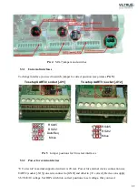
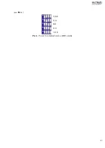
Page 22: ...23 see Pic 6 3 6 V 5 V 6V 8 V 10 V Pic 6 Power for external device DIP switch ...
Page 53: ...54 Pic 48 Routing configuration example ...
Page 54: ...55 Pic 49 Routing screenshots ...
Page 59: ...60 2 Set COM port number UART port must be configured and assigned to COM client on ...
Page 66: ...67 Pic 61 Setting up RAY 1 as External module by example ...
Page 75: ...76 Pic 71 Records in archives section Archives Configutation ...


