15/24
NT00000604-JBRB-ECOWATT-AN-191202
JBRB ECOWATT
®
30 to 92 Three-phase
L1 L2 L3
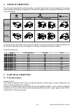
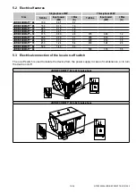
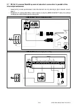
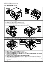
To access the on-off switch’s terminals, unscrew the door’s 2 M8 screws using a 13mm spanner.
Add a cable gland to the power cable and connect it to the on-off switch terminals.
5.4 Pressure switch connection
•
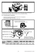
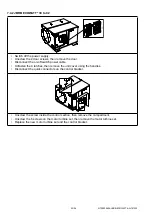
Open the unit panel by unscrewing both screws with a 13mm spanner.
• Add the 2nd cable gland to the cable.
•
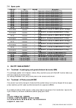
Open the pressure switch cowl and connect the wires.
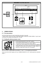
• Access to terminals and settings
•
Lightly lift to remove the base plate cover
1
2
3
Ventilation fault
indicator light
Normal operation
indicator
light
Max. 250Vac power supply
Adjusting disk
State of contact at rest
1
2
3
Switches for measurement
of pressure ΔP > at threshold
ΔP0 of pressure switch setting
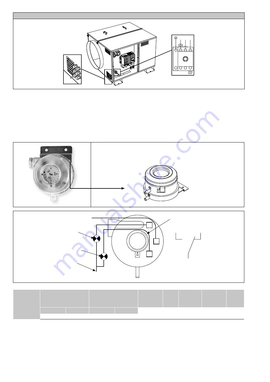
Interrupting
capacity
Resistive load
(cos
Ø
=1)
Inductive load
(cos
Ø
=0.6)
Mechanical
lifespan
Cable
gland
Protection
index
Pressure
connection
Mass
Under 250Vac Under 30Vac Under 250Vac Under 30Vac > 10 million
cycles
1xPg11 IP54 with
cowl
Ø6.2mm
Approx.
10 g
5A
4A
0.8A
0.7A


