background image


3/24

 NT00000604-JBRB-ECOWATT-AN-191202

1. 

GENERAL INFORMATION

1.1  Warnings

This product has been manufactured according to rigorous technical rules of safety in conformity with EC 

standards. The EC declaration may be downloaded from the Internet site (address given on the last page).

Before installing and using this product, carefully read these instructions, which contain important indi

-

cations for your safety and the user’s safety during the installation, commissioning and maintenance of 
this product. Once the installation is terminated, keep this manual handy nearby the machine for future 
consultation.

This product must be installed (installation, connections, commissioning, maintenance) and all other  inter

-

ventions performed by a professional applying recognized good practice procedures, and respecting the 

standards and safety regulations in force. The installation must be made in accordance with the prescrip

-

tions indicated in the Electromagnetic Compatibility (EMC) and Low Voltage (LV) Directives.

We advise all people exposed to risks to scrupulously respect the accident prevention standards. The ma-
nufacturer may not be held liable for any human injury and/or material damage resulting from the non-res-
pect of the safety instructions or from a change made on the product.

JBRB ECOWATT

®

 units are intended for controlled mechanical ventilation or air recycling applications on 

tertiary premises:

• 

Indoor or outdoor installation

• 

Environmental temperature: -20°C / +50°C

• 

Relative humidity: max. 95% without condensation

•  Non-potentially-explosive atmosphere
• 

Low-salinity atmosphere, without corrosive chemical agents

1.2  Safety instructions 

• 

Put on appropriate PPE (Personal Protective Equipment) before any work.

•  Before installing the ventilation unit, make sure that the bracket and the location are strong enough 

to bear the weight of the unit and any accessories. 

• 

Do not open the access panels without having cut off the padlockable switch-disconnector included 

in the unit.

• 

If work has to be carried out on the device, cut off the power supply on the main circuit breaker and 

make sure that nobody can accidentally turn it back on.

•  Make sure that moving parts are stationary.
• 

Check that the ventilation motor is not accessible via the connection brackets. (connection sheath 

or protective shield).

Before starting, check the following points:

•  Make sure that the device does not contain any foreign bodies. 
•  Check that all the components are mounted in their original positions.
•  Check manually that the fans do not rub or get blocked.
•  Check the connection of the earth electrode. 
•  Check that the access hatch is properly closed.

1.3  Reception - Storage

In case of short shipment, non-conformity, and/or total or partial damage to the products delivered, the 

Buyer must, in accordance with article 133-3 of the French Commercial Code, add written reservations to 

the carrier’s delivery slip and confirm them within 72 hours by registered letter with acknowledgement of 

receipt with a duplicate for the seller. If the equipment is received without express reservation, the Buyer 

has no subsequent recourse against us. 

The product must be stored protected from weather, shocks and soiling due to splashing of any kind during 

its transport from the supplier to the final customer and on the site before installation.

Summary of Contents for JBRB ECOWATT 04

Page 1: ...STALLATION WIRING COMMISSIONING MAINTENANCE AFNOR CERTIFICATION ISO 14001 Environnement AFNOR CERTIFICATION ISO 9001 Q u a l i t é JBRB ECOWATT Tertiary buildings ventilation ECM motor extractor unit 400 C 1 2hr C4 approved Efectis certificate EFR 16 002341 ...

Page 2: ...ON 13 5 1 Prior precautions 13 5 2 Electrical features 14 5 3 Electrical connection of the local on off switch 14 5 4 Pressure switch connection 15 5 5 Relay electrical connection ventilation fault 16 5 6 REB ECOWATT or CVF remote electrical connection 17 6 COMMISSIONING 18 6 1 Prior precautions 18 6 2 Setting the volume pressure curve 18 7 MAINTENANCE 19 7 1 Prior precautions 19 7 2 Maintenance f...

Page 3: ... atmosphere Low salinity atmosphere without corrosive chemical agents 1 2 Safety instructions Put on appropriate PPE Personal Protective Equipment before any work Before installing the ventilation unit make sure that the bracket and the location are strong enough to bear the weight of the unit and any accessories Do not open the access panels without having cut off the padlockable switch disconnec...

Page 4: ...ze 04 to 38 or 2 omega cross piec es sizes 48 to 92 High performance galvanised steel backward INTZ installed wired lockable safety switch BDEZ pressure switch installed connected to the aeraulic network to adjust on site ECM direct current motor outside airflow 04 to 22 IP44 class B single phase 230V 50Hz 30 38 48 70 82 IP54 class F single phase 230V 50Hz 30 38 48 70 92 IP54 class F three phase 4...

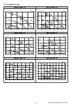
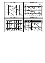
Page 5: ...50 100 150 200 250 0 200 400 600 800 1000 1200 P Pa stat Δ Pabs W 100 75 50 Qv m3 h 41 73 38 71 37 71 Qv m3 h 0 100 200 300 400 500 600 0 100 200 300 400 500 600 0 500 1000 1500 2000 2500 P Pa stat Δ Pabs W 100 75 50 43 75 42 75 44 77 JBRB ECOWATT 30 JBRB ECOWATT 38 100 75 50 Qv m3 h 0 100 200 300 400 500 600 700 0 100 200 300 400 500 600 700 0 500 1000 1500 2000 2500 3000 3500 P Pa stat Δ Pabs W ...

Page 6: ... h 100 200 300 400 500 600 700 Pstat Pa 200 400 600 800 1000 1200 1400 Pabs W 100 75 50 51 79 51 79 53 81 JBRB ECOWATT 82 JBRB ECOWATT 92 0 100 200 300 400 500 600 0 300 600 900 1200 1500 1800 0 1000 2000 3000 4000 5000 6000 7000 8000 9000 P Pa stat Δ Pabs W 100 75 50 Qv m3 h 50 80 49 78 52 81 0 100 200 300 400 500 600 700 800 0 300 600 900 1200 1500 1800 2100 2400 0 2000 4000 6000 8000 10000 P Pa...

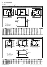
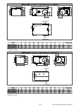
Page 7: ... 767 683 701 511 355 709 661 252 237 252 239 45 JBRB ECOWATT 30 1 019 820 873 568 400 892 797 267 271 267 271 64 JBRB ECOWATT 38 1 153 938 971 631 500 1 036 907 306 331 306 331 78 IS version 27mm JBRB ECOWATT 48 70 82 92 horizontal discharge L M configuration H G C F C Ø D1 A Ø D1 E J I C F B1 B Sense of the air Sense of the air Sense of the air Only available on modular version M configuration Mo...

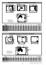
Page 8: ...98 661 239 219 252 239 45 JBRB ECOWATT 38 1 468 1 024 631 500 400 1 396 908 306 281 306 331 83 IS version 27mm JBRB ECOWATT 48 82 92 horizontal discharge D configuration C F B Ø D2 Ø D2 C Ø D1 A E G H J I C F B Sense of the air Sense of the air Sense of the air Model A B C D1 D2 E F G H I J Weight kg JBRB ECOWATT 48 1 490 1 105 800 560 450 990 918 433 270 433 330 135 JBRB ECOWATT 82 1 813 1 237 97...

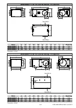
Page 9: ... 355 709 661 252 237 236 271 38 JBRB ECOWATT 30 973 820 873 565 400 892 797 267 271 248 286 64 JBRB ECOWATT 38 1 106 938 971 637 500 1 036 907 306 331 315 350 78 IS version 27mm JBRB ECOWATT 48 70 82 92 vertical discharge L M configuration H G F A Ø D1 E F B1 B J I Sense of the air Sense of the air Sense of the air Only available on modular version M configuration Model A B B1 C D1 E F G H I J Wei...

Page 10: ...98 661 239 219 236 271 45 JBRB ECOWATT 38 1 426 1 025 637 500 400 1 396 909 306 281 315 350 83 IS version 27mm JBRB ECOWATT 48 82 92 vertical discharge D configuration C F B Ø D2 Ø D2 C Ø D1 A E G H J I C F B Sense of the air Sense of the air Sense of the air Model A B C D1 D2 E F G H I J Weight kg JBRB ECOWATT 48 1 444 1 105 800 560 450 990 918 433 270 320 340 135 JBRB ECOWATT 82 1 767 1 237 970 ...

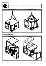
Page 11: ...o move the unit These handles are only to open the unit cover JBRB ECOWATT 04 to 38 JBRB ECOWATT 48 to 92 3 3 Choice of location JBRB ECOWATT 04 to 38 JBRB ECOWATT 48 to 92 C C C C C C Leave the height of the unit above the unit and on the door side for device commissioning and maintenance ...

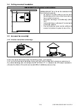
Page 12: ...tical discharge authorised if connected to an aeraulic network The unit fastening mode must be sufficient to ensure it is held well in place in case of fire 3 5 Accessories assembly 3 5 1 Circular connection to discharge Fasten the sealed flat bracket using 6 self drilling screws not supplied For a unit not connected to discharge add a vent cowl CP to enable 360 exhaust air outlet around the verti...

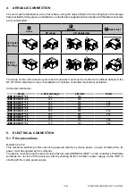
Page 13: ...ulablecoudéà90 doubleaspirationà90 M Orientation rejet horizontal Orientation rejet vertical L D M Orientation rejet horizontal Orientation rejet vertical Enligne L Doubleaspiration D Modulablecoudéà90 doubleaspirationà90 M Orientation rejet horizontal Orientation rejet vertical Enligne L Doubleaspiration D Modulablecoudéà90 doubleaspirationà90 M Orientation rejet horizontal Orientation rejet vert...

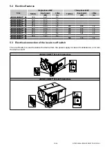
Page 14: ... 6 JBRB ECOWATT 30 315 0 60 2 6 315 0 60 1 2 JBRB ECOWATT 38 355 0 70 3 1 355 0 70 1 3 JBRB ECOWATT 48 400 0 72 3 1 400 0 72 1 5 JBRB ECOWATT 70 450 1 24 5 4 450 1 24 2 6 JBRB ECOWATT 82 500 1 40 6 0 JBRB ECOWATT 92 500 1 70 3 5 5 3 Electrical connection of the local on off switch The on off switch is used to isolate the device from the power supply in case of maintenance or to turn the device on ...

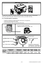
Page 15: ...re switch cowl and connect the wires Access to terminals and settings Lightly lift to remove the base plate cover 1 2 3 Ventilation fault indicator light Normal operation indicator light Max 250Vac power supply Adjusting disk State of contact at rest 1 2 3 Switches for measurement of pressure ΔP at threshold ΔP0 of pressure switch setting Interrupting capacity Resistive load cos Ø 1 Inductive load...

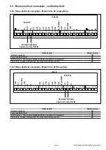
Page 16: ...y shut off NC On Off contact The wheel is stationary but the conductor is powered up NC Phase loss In case of phase loss the wheel may continue to turn NC 5 5 2 Relay electrical connection Model 30 to 92 three phase 1 2 3 4 5 6 7 8 9 10 11 12 13 14 15 16 17 18 19 24V Fire 24V Start Stop Speed Output GND 24V GND An2 10V GND An1 NO COM NC Relay fault Ventilation fault wiring Open contact Stop of the...

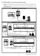
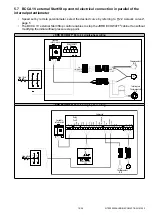
Page 17: ... N 1 2 3 4 5 P JBRB ECOWATT 30 to 82 single phase wiring Compacto Relay fault Lockable safety switch REB ECOWATT CVF U V W U V W B A 24V Start Stop Fire 24V Sped Output GND 24V GND An2 5V Pot GND An1 NO COM NC L N 1 2 3 4 5 6 7 8 9 1011 12 13 1415 16171819 2021 2223 24 2526 27 U V W 1 2 3 4 5 P L N Gnd Consigne 0 5V 5V JBRB ECOWATT 30 to 92 three phase wiring Invento Relay fault Lockable safety sw...

Page 18: ...nt JBRB ECOWATT 04 to 22 single phase wiring M 10V Entrée 0 10V Gnd N L Thermocontact N O Thermocontact N O Interrupteur REB ECOWATT 10V Consigne0 10V Gnd Lockable safety switch 1 2 3 4 5 P CVF N L N L Stop Start 13 14 33 34 JBRB ECOWATT 30 to 82 single phase wiring 1 2 3 4 5 6 7 8 9 10 11 12 13 14 15 16 17 18 19 20 21 22 23 24 25 26 27 U V W 24V Fire 24V Start Stop Speed Output GND 24V GND An2 5V...

Page 19: ... switch defined according to IEC947 3 695 2 1 must be open and locked in this position according to NF C 15 100 6 2 Setting the volume pressure curve Put the switch disconnector to the OFF position Set the desired airflow pressure curve by turning the adjusting po tentiometer referring to 2 2 Aeraulic curves page 5 In general the curves included in the manual mean the speed can be pre selected but...

Page 20: ...JBRB ECOWATT Single phase 30 to 82 Potentiometer graduation Voltage V on controller terminal 9 JBRB ECOWATT 30 JBRB ECOWATT 38 JBRB ECOWATT 48 JBRB ECOWATT 70 JBRB ECOWATT 82 0 0 200rpm 200rpm 200rpm 200rpm 200rpm 2 1 610rpm 530rpm 460rpm 460rpm 430rpm 4 2 1 020rpm 855rpm 720rpm 720rpm 660rpm 6 3 1 430rpm 1 180rpm 980rpm 980rpm 890rpm 8 4 1 840rpm 1 500rpm 1 240rpm 1 240rpm 1 120rpm 10 5 2 250rpm ...

Page 21: ...bing between mobile parts and stationary parts Controller Check the connections particularly the connection to the earth electrode Tighten the terminals if necessary check the ampere rating On off switch Check the connections particularly the connection to the earth electrode Tighten the terminals if necessary Duct networks Check seals Clean if necessary Pressure inlet Check aeraulic connections C...

Page 22: ...the motor turbine set then remove the motor turbine set Position the new motor turbine set on the 2 stops Screw on the 4 M8x20 screws without tightening them Screw on the 2 M8x80 screws in the motor bracket and adjust the housing wheel play by screw ing unscrewing these screws Tighten the 4 M8x20 screws then remove the 2 M8x80 screws Replace the control compartment reconnect the 3 quick connectors...

Page 23: ...on off switch power cable Unfasten the 4 latches then remove the unit cover using the handles Disconnect the quick connectors on the control bracket Unscrew the screw inside the control section then remove the compartment Unscrew the 6 screws on the motor turbine set then remove the motor turbine set Replace the new motor turbine set and the control bracket ...

Page 24: ...ontroller for JBRB ECOWATT 30 Three phase 157112 Controller 1 COMPACTO 08 Controller for JBRB ECOWATT 38 Single phase 1571161001 Controller 1 INVENTO S15 Controller for JBRB ECOWATT 38 Three phase 157113 Controller 1 COMPACTO 08 Controller for JBRB ECOWATT 48 Single phase 1571161002 Controller 1 INVENTO S15 Controller for JBRB ECOWATT 48 Three phase 157114 Controller 1 COMPACTO 11 Controller for J...

Reviews: