3
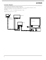
4.1 POWER SUPPLY OF VIDEO DOOR ENTRY UNITS IN PARALLEL (INTERMITTENT SERVICE)
The power supply unit must be inserted in the video door entry system to switch on two or more video door entry units simultaneously: the first monitor
must be connected directly to the system’s power supply unit, all the subsequent ones must each be powered by a power unit Art. 02032.
Make the connection as in the diagram representing the connection of just the cond and - ; then complete the connections following the diagram
supplied with the power units Art. 6580, 6581 and 6680, bearing in mind that, to switch on 2 or more video door entry units simultaneously it is sufficient
to connect in parallel the terminals no. 8 (call) of the standard monitors or the terminals 6E of the Sound System series monitors, etc.
Input voltage: +I - , 10 to 20Vd.c.
Output voltage: +U - , 18Vd.c. 0.8A not stabilized
N.B. Make a bridge between the terminals A and B.
4. CONNECTION DIAGRAMS
The following diagrams illustrate some examples of the main applications using the power supply unit 02032.
Connection Diagrams
6
1
3
2
4
5
11
8
7
9
10
V
14
13
M
14
6
2
1
3
4
5
10
8
7
9
11
13
V
M
14
6
2
1
5
4
3
10
9
7
8
13
12
12
12
11
M
V
oppure
CN2
6E
6S
6P
6
7
AU
2
3
5
CN1
CN1
M
+A
CH
+D
-
+
V2
V3
M
V1
1
CH
6
6P
6S
AU
3
5
6E
1
2
CN1
7
CN2
V3
+
+D
-
+A
V1
M
M
V2
CH
6
6S
6P
AU
3
6E
5
2
1
7
CN1
CN2
V3
+
-
+D
+A
V1
V2
M
M
V3
7
2
1
3
5
4
6
11
9
8
10
12
13
V1
M
V2
V3
V3
7
2
1
3
5
4
6
11
9
8
10
12
13
7
2
1
3
5
4
6
11
9
8
10
12
13
V1
M
V2
V1
M
V2
- +U +I
B C
A
D
PRI
1
2
3
CH
- +
S
V
+
1
2
3
-
S
V
CH
+ -
6 5
PRI
+U
-
+I A B C D
V
V
PRI
- +U +I A B
D
C
CH V
-
+
6
V
5
POWER SUPPLY
ART. 02032
NETWORK
MONITOR
GIOTTO series
5600 series
5601 series
5604 series
6300 series
6500 series
Max 2 monitor
Art. 6300
Art. 6301
Art. 6303
NETWORK
POWER SUPPLY
ART. 02032
TO THE OTHER MONITORS
TO THE OTHER MONITORS
TO POWER SUPPLY
Art. 6580 - 6581 - 6680
TO POWER SUPPLY
Art. 6580 - 6581 - 6680
20550 + 01961
01951 - 01953


