CARATTERISTICHE TECNICHE DEL L’ALI MEN TA TO RE ART. 938A
Alimentatore per impianti intercomunicanti con posto ester no mono o plu-
ri-familiari. È munito di triplo generatore di nota elettronico (sound system)
che si sostituisce alla tra di zio na le chiamata in alternata su ronzatore o
campanello. Il se gna le sonoro di spo ne di 3 tonalità differenziate per met-
ten do così l’individuazione immediata del punto da cui si chiama (chia-
ma ta dal posto esterno, chia ma ta fuoriporta, chiamata intercomunicante).
Negli impianti non è più ne ces sa rio quindi inserire suonerie tradizionali
poichè il suono viene diffuso da un’unico al to par lan te pre sen te all’interno
del citofono.
Alimentatore con custodia in materiale termoplastico gri gio, pre di spo sto
per mon tag gi su quadri con barra DIN ad omega con un ingombro di otto
moduli oppure con fissaggio a parete tramite tasselli.
PRINCIPIO DI FUNZIONAMENTO
Al suono della chiamata esterna, si solleva il microtelefono e si comunica
direttamente con l’esterno. Trascorsi circa 9 minuti dall’inizio della con-
ver sa zio ne un dispositivo elettronico riporta i citofoni in posizione interno
ed è quindi necessario che venga effettuata una seconda chia ma ta per
conversare nuovamente con il posto esterno. Per effettuare la con ver sa-
zio ne interna, prima si solleva il microtelefono e poi si preme il pulsante
relativo al ci to fo no col quale si desidera comunicare; il posto esterno
rimane cosí scollegato. Se durante una comunicazione ester na si vuole
effettuare una chiamata verso un utente interno basta premere il pulsante
relativo all’interno.
Per rispondere ad una chiamata proveniente dall’esterno durante una
conversazione interna è necessario riporre entrambi i microtelefoni e poi
sollevarne uno. È possibile attivare la funzione di segnale di chiamata in
targa collegando il morsetto CT al morsetto C1. Questa funzione permette
di attivare un segnale sul posto esterno ogni volta che si esegue una chi-
amata o quando si esegue l’autoaccensione.
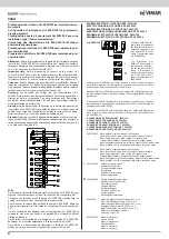
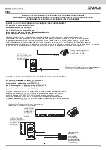
ISTRUZIONI PER IL COLLEGAMENTO
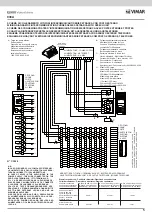
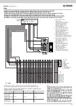
Lo schema rappresenta il collegamento del massimo numero di citofoni.
Per collegarne un numero inferiore procedere come nelle istruzioni sot-
toriportate (con tre citofoni si utilizzano apparecchi Art. 6200 a 4 pulsanti
di cui 2 pulsanti supplementari);
- il primo pulsante (morsetto 7) per la serratura
- il secondo pulsante (morsetto 8) per servizi ausiliari
Gli altri due pulsanti corrispondenti ai morsetti 9-10 per le chiamate inter-
comunicanti. Si collegheranno quindi le prime tre morsettiere dal morsetto
1 al morsetto 10.
TECHNICAL CHARACTERISTICS OF POWER SUPPLY ART. 938A
Power supply for intercommunicating system with single or multi-family
speech unit. Fitted with a electronic 3-tone generator (sound system)
which replaces the traditional alternating current call on a buzzer or bell.
The sound signal has 3 different tones which make it possible to immedi-
ately identify which point is calling (call from speech unit, call from outside
door, intercommunicating call). This solution also means it is no longer
necessary to install traditional bells since the sound is produced by a sin-
gle loudspeaker in the phone. Power supply in grey ABS housing; preset
for mounting on cases with DIN 8-module support or with expanding plugs
with screws.
OPERATING PRINCIPLE
When a call is made from the outdoor speech unit, lift the handset to
communicate directly with the outdoor speech unit. 9 minutes after the
start of the conversation an electronic device returns the interphone to in-
ternal mode, thereby making it necessary to make a second call in order to
continue the conversation with the external speech unit. To make internal
calls, raise the handset and press the corresponding interphone button.
In this way the external speech unit remains disconnected. If, during a
conversation with the external speech unit, you wish to call an internal unit,
simply press the corresponding interphone button.
To answer a call coming from the speech unit during an internal conversa-
tion hook both handsets and then lift one of them.
It is possible to activate the function of call signal on the panel by connect-
ing terminal C1.
This function allows a signal to be activated on the speech unit any time a
call is made and when the selfactivation is carried out.
I
GB
F
CARACTÉRISTIQUES TECHNIQUES DE L’ALIMENTATION ART. 938A
Alimentation pour installations intercommunicantes avec po ste extérieur mono
ou pluri-familial. Il est doté d’un triple générateur de note électronique qui rem-
place l’appel traditionnel en courant alternatif sur ronfleur ou sonnette (sound
system). Le signal sonore dispose de 3 tonalités differénciées, ce qui permet
d’identifier immédiatement l’endroit d’ou vient l’appel (appel du poste extérieur,
appel hors porte, appel intercommunicant). Il n’est donc plus nécessaire, dans
les installations, de brancher des sonneries traditionelles car le son est diffusé
par un seul haut-parleur présent à l’intérieur de l’interphone.
Alimentation avec boîtier en matière thermoplastique grise; prédisposée pour
montages su barre DIN à 8 modules ou pour le fixage à paroi avec vis à
goujons.
PRINCIPE DE FONCTIONNEMENT
A l’appel externe, décrochez le combiné pour communiquer avec le correspon-
dant extérieur. 9 minutes après le début de la conversation, un dispositif élec-
tronique ramène les postes en position interne et vous devez nécessairement
provoquer un deuxième appel pour pouvoir de nouveau converser avec le
poste externe. Pour converser en interne, décrochez d’abord le combiné puis
appuyez sur le poussoir du poste interne souhaité; le poste externe reste ainsi
débranché. Si pendant une communication externe, vous voulez converser
avec un poste in ter ne, il vous suffira d’appuyer sur le poussoir du poste in-
ter ne désiré.
Pour répondre à un appel provenant de l’extérieur pendant une conversation
interne il faut accrocher les deux combinés et ensuite soulever n’importe quel
des deux.
Il est possible d’activer la fonction de signal d’appel dans la plaque de rue en
raccordant la borne C1. Cette fonction permet d’activer un signal sur le poste
externe toutes le fois qu’on rappelle et lorqu’on effectue l’autoenclenchement.
INSTRUCTIONS DE BRANCHEMENT
Le schéma montre le branchement du nombre maximum de postes d’appar-
tement. Si l’installation prévoit moins de postes, suivez les instructions ci-des-
sous (avec 4 postes, utilisez les Art.6200 à 3 boutons dont 2 supplémentaires):
- le premier bouton (borne 7) pour la commande de la gâche;
- le deuxième bouton (borne 8) pour les services auxiliaires.
Les autres deux boutons correspondent aux bornes 9 et 10 pour les appels
intercommunicants. Vous devrez donc connecter les premiers trois borniers
de la borne 1 à la borne 10.
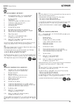
CONNECTION INSTRUCTIONS
The wiring diagram indicates the connections required for the maximum num-
ber of interphones. If you do not wish to connect all the interphones, follow the
instructions indicated below. To connect three interphones, use units Art 6200
supplied with 4 buttons, two of which control the supplementary functions.
The first button (terminal 7) controls the door lock release function.
The second button (terminal 8) controls the auxiliary services.
The two supplementary buttons are connected to terminals 9-10 and control
intercommunicating calls. It is therefore necessary to connect terminals 1 to
10 on the first three terminal boards.
2
938A


