Viale Vicenza, 14
36063 Marostica VI - Italy
www.vimar.com
49400702B0 02 1902
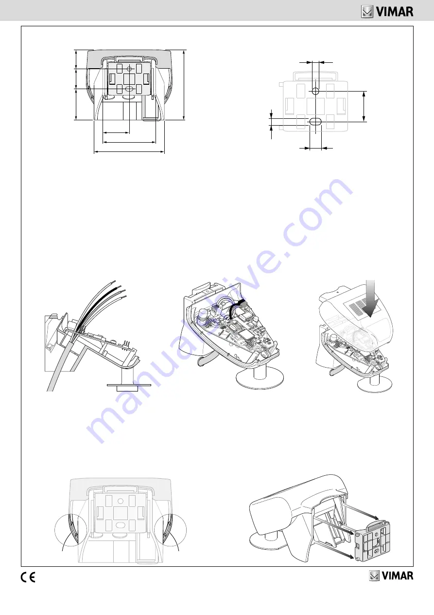
6. Forare la guarnizione posta sul retro della scatola per permettere il passaggio del cavo; la guarnizione non deve essere rimossa poiché previene even-
tuali infiltrazioni d’acqua. Posizionare la guaina del cavo sotto la scheda e far passare verso l’alto solo i cavi di collegamento attraverso gli appositi fori.
Perforate the seal on the back of the box to allow the cable to pass through; the seal should not be removed since it prevents water from infiltrating.
Place the cable sheath under the circuit board and feed only the connecting cables upwards through the holes.
Percer le joint présent à l’arrière de la boîte pour permettre le passage du câble ; ne pas retirer le joint car il évite les infiltrations d’eau. Placer la gaine du
câble sous la carte et ne faire passer par le haut que les câbles de raccordement à travers les orifices.
7. Collegare i cavi di alimentazione e del bus e chiudere la scatola appli-
cando il coperchio sul fondo; il bloccaggio deve essere comfermato da un
“click”. Verificare il perfetto incastro del coperchio nella parte inferiore.
Connect the cables for the power supply and bus and close the box by
fitting the cover on the bottom; locking must be confirmed by a “click”.
Check the cover fits in properly at the bottom.
Brancher les câbles d’alimentation et du bus puis fermer la boîte en
posant le couvercle sur le fond; le couvercle résulte verrouillé lorsque
vous entendez un déclic. S’assurer que le couvercle est encastré cor-
rectement dans la partie inférieure.
8. Spostare la scatola nella parte superiore del supporto installato; i denti di
giunzione devono innestarsi nelle guide del la scatola. Per togliere il sensore
dal supporto, tirarlo verso l’alto ed estrarlo opponendosi all’ arresto a scatto.
Move the box to the top of the installed mounting frame; the coupling teeth
should engage in the box guides. To remove the sensor from the mounting
frame, pull it upwards and take it out against the resistance of the fastener.
Déplacer la boîte dans la partie supérieure du support installé ; les dents de jonc-
tion doivent s’emboîter dans les guides de la boîte. Pour enlever le capteur du sup-
port, le tirer vers le haut et le dégager du cran d’arrêt en tirant dans le sens inverse.
4. Retro del supporto e disposizione dei fori di fissaggio - Back of the mounting frame and layout of the fixing holes - Face arrière du support et disposition
des orifices de fixation
5. Togliere il coperchio con cautela per evitare di staccare il cavo di collegamento tra la scheda posta sul fondo ed il sensore di pioggia nel coperchio.
Far passare il cavo alimentazione e quello per la connessione al bus attraverso le guarnizioni di gomma poste in fondo al sensore di precipitazioni e col-
legarli agli appositi morsetti (AUX e bus TP).
Remove the cover carefully to avoid detaching the connection cable between the circuit board on the bottom and the rain sensor in the cover.
Pass the power cable and the bus connection cable through the rubber seals at the back of the precipitation sensor and connect them to the special terminals (AUX and TP bus).
Enlever le couvercle avec précaution pour éviter de détacher le câble de raccordement entre la carte qui se trouve sur le fond et le capteur de pluie dans le couvercle.
Faire passer le câble d’alimentation et celui de connexion au bus à travers les joints en caoutchouc se trouvant au fond du capteur des précipitations et
les brancher sur les bornes correspondantes (AUX et bus TP).
28,75
19
22
35
76
78
57,5
7,5
Ø 4,5
22
4,5
click
click
1


