Viale Vicenza, 14 - I 36063 Marostica VI
Tel. +39 0424 488 600 - Fax (Export) +39 0424 488 709
www.vimar.eu
ENGLISH
Instruction sheet
Eikon
20430
Idea
16915
Plana
14430
Well-contact Plus
Electronic thermostat for ambient air temperature control (heating and air conditioning) of 2 independent zones, KNX standard, 1 NO relay output 4
A 24 V~, 1 input for temperature sensor 20432-14432, 1 programmable digital input - 2 modules.
THERMOSTAT
OFF
A B
C D
OFF
A B
C D
OFF
A B
C D
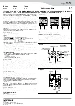
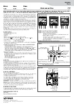
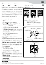
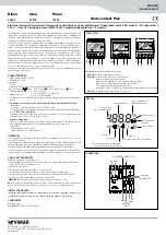
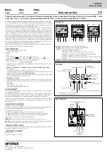
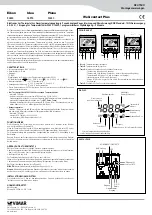
FRONT VIEW.
Plana
Idea
Eikon
• Button A
: decrease in temperature set-point.
• Button B
: increase in temperature set-point.
• Button C
: selection of the thermostat to view/monitor:
- thermostat A (viewing and monitoring);
- thermostat B, if enabled; icon ext lit (viewing and monitoring);
- KNX sensors 1-8 temperature (if present, only viewing);
- NTC sensor inside the thermostat A (viewing);
- external NTC sensor connected to the thermostat terminal (if present, only viewing).
• Button D
: increase/decrease in the speed of the fan-coil.
ext
DISPLAY.
Room temperature
Unit of measurement
(Celsius/Fahrenheit)
Air conditioning/
Heating
Fan-coil speed
Guest out of room function (Stand-by)
Antifreeze
System off
Comfort temperature changed by the
customer from set-point by default
Economy
Device blocked
(not controllable locally)
Thermostat B on
The thermostat is suited for ambient temperature control (heating and air-conditioning) and it can
interact with other thermostats (whose measured temperatures can be used to determine the
“weighted” temperature) and with a supervision centre (PC in reception or technical room where,
for example, the Well-contact Suite software is installed).
The device is able to manage 2 temperature zones completely independently; in practice it is as
if it were composed of two independent thermostats monitoring one zone each (thermostats A
and B). The thermostat A and the thermostat B will manage the corresponding heating/air-con-
ditioning systems based on the average of the temperature values measured by the temperature
sensors that can be associated with A and B. The thermostat is provided with an NC or NO
programmable relay that can be used for generic use (switching on light/closing zone solenoid
valve/activating electric towel heater, etc.) or to control speed 1 of the fan-coil managed by the
thermostat A (or alternatively by the thermostat B). In addition, it has an NC or NO programmable
digital input that can be used for applications such as, for example, detecting an open window
or for other general uses for one or for both thermostats A/B.
The device is equipped with a display and four front buttons to control the temperature set-point
and the speed of the fan-coil.
CHARACTERISTICS.
• Supply voltage: BUS 29 V SELV.
• Consumption: 10 mA
• Terminals:
- TP bus;
- digital input for NO or NC contact (with no potential, SELV);
- NO relay output ( 24 V~ SELV 4 A cos 1; 24 V~ SELV 2 A cos 0.6);
• Operating temperature: -5 °C - +45 °C (inside)
±0.5 °C between 15 °C and 30 °C
• Reading accuracy:
±0.8 °C at the extremes
• This device contains only SELV circuits that must be kept separate from circuits with dangerous
voltage.
•
Temperature sensors that can be managed via the thermostat 20430-16915-14430.
- Internal NTC
- Possibility of connecting an external NTC art. 20432-14432
- Possibility of using the temperature values sent over the bus from 8 different KNX temperature
sensors (
DPT_Value_Temp data
).
- Maximum length of the connecting cable of the external NTC: 60 m. Use a twisted cable with
a minimum cross-section of 0.5 mm
2
(art. 01840)
• Reference temperature
For each of the two thermostats A and B the reference temperature for the climate control is
the weighted average among all the available temperature sources (if present):
- Internal NTC
- External NTC art. 20432-14432
- via bus (KNX sensors 1-8 temperature)
OPERATION.
The configuration of the thermostat, physical address, parameters, its operation, etc., is done
with the ETS software.
If the thermostat is loaded with an incorrect ETS application, the red LED on the back of the
device will flash and all the LCD segments will blink on the display (“device type” error).
To restore the desired configuration, load the device with the correct ETS application.
The user, by means of the front buttons, will be able to change the temperature set point and the
speed of the fan-coil; changing these parameters forces the thermostat onto manual operation.
USING THE THERMOSTAT.
Using the thermostat it is possible to set:
• the temperature set-point in the room (the change can only be made within certain limits set
by the control centre or reception, etc.);
• the speed of the fan-coil.
To change the temperature press the
+
or
-
button twice:
• on pressing it the first time the display will show the currently set temperature;
• on pressing it the second time the increase/decrease in the displayed value will begin.
The selection of the thermostat
B
is made with the button
F
.
IMPORTANT
: Max length of the cable for the connection of the inputs = 30 m.
Note
: In the phase of installation provide for cable connection lengths that allow extracting the
device from the flush mounting box so as to be able to access the configuration button.
INSTALLATION RULES.
Installation should be carried out in compliance with the current regulations regarding the
installation of electrical systems in the country where the products are installed.
CONFORMITY.
EMC directive.
Standards EN 50090-2-2, EN 50428.
CONNECTIONS.
BUS line
Common
input
Relay
C NO
Input
LED
CONFIGURATION BUTTON
Imput for
external NTC

