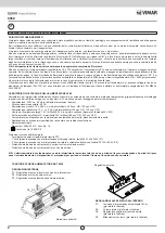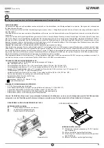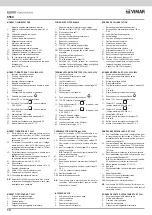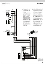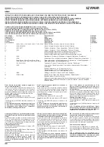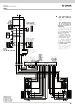
MORSETTI CITOFONO ART. 6201
1: Fonica e chiamata da targa
2: Ingresso per autoaccensione
3: Comune fonica
5: Chiamata fuoriporta
6: Collegamento per ripetitore di chiamata
MORSETTI ALIMENTATORE
- : Morsetto negativo alimentazione monitor
+: Morsetto positivo alimentazione monitor 18V c.c.
0,8A
P2: Chiamata elettronica fuori porta
AU: Autoaccensione
2: Comune fonica citofoni/monitor
5: Altoparlante posto esterno
6: Microfono posto esterno
8: Altoparlante posto esterno
- : Negativo alimentazione telecamera
+T: Alimentazione telecamera 13V c.c. 0,3A
P1: Chiamata elettronica dal posto esterno
S1: Collegamento alla serratura elettrica
0: 0V (con riferimento al morsetto 15)
15: Tensione 15V rettificati 250mA servizio
continuo, per alimentazione serratura e lampade
illuminazione
tasti (3x24V 3W max)
MORSETTI MONITOR ART. 6000
V1: Per impianti con cavo coassiale, entrata per il col-
legamento del cavo video di 75 Ohm. Per impianti
senza cavo coassiale, entrata per il collegamento
del segnale V1.
V2: Per impianti con coassiale, uscita per il collega-
mento del cavo video di 75 Ohm oppure per il
collegamento della resistenza di carico di 75 Ohm
nell’ultimo monitor del montante.
V3: Per impianti senza cavo coassiale, entrata per il
collegamento del segnale V2.
N.B.
Per impianti con cavo coassiale il morsetto V3
va cortocircuitato sul morsetto M.
M: Massa relativa ai morsetti V1, V2, V3.
+A: Non utilizzato
+: Positivo alimentazione (tensione minima 15V c.c.)
-:
Negativo alimentazione
+D: 12V c.c. per distributore video
CH: Chiamata per accensione monitor
CN2: Connettore per interfaccia monitor
N.B.
Il monitor Art. 6000 dispone sul retro di un microin-
terruttore per il settaggio collegamento “cavo coas-
siale/senza cavo coassiale”
MORSETTI MONITOR ART. 6306, 6506, 6326
1: Ingresso per autoaccensione
2: Fonica e chiamata da targa
3: Non collegato
4: Ingresso chiamata fuoriporta
5: Negativo alimentazione
6: Positivo alimentazione (tensione minima in arrivo
15V c.c.)
7: Non collegato.
8: Collegamento per ripetitore di chiamata
9: Pulsante per servizi ausiliari
10: Uscita 12V c.c. per distributore video
11: Contatto N°1 pulsante
(carico massimo
0,5A 24Vcc)
12: Contatto N°2 pulsante
(carico massimo
0,5A 24Vcc)
13: Alimentazione LED verde
V1: Entrata per il collegamento del segnale V1.
V2: Non collegato
V3: Entrata per il collegamento del segnale V2.
M: Massa relativa ai morsetti V1, V3.
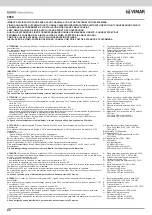
TERMINALS FOR MONITOR TYPE 6306, 6506, 6326
1: Input for self-start
2: Audio and call from entrance panel
3: Not connected.
4: Input for outdoor call
5: Power supply negative
6: Power supply positive (minimum input voltage 15V
DC)
7: Not connected.
8: Connection for call repeater
9: Push-button for auuxiliary services “
”
10: 12V DC output for video distributor
11: Push-button contact N. 1 “
” (maximum load
0,5A 24V D.C.)
12: Push-button contact N. 2 “
” (maximum load
0,5A 24V D.C.)
13: Green LED supply voltage
V1: Input for connection of the V1 signal.
V2: Not connected.
V3: Input for connection of the V2 signal.
M: Ground for terminals V1, V3.
POWER SUPPLY TERMINALS
- : Negative terminal of monitor supply voltage
+: Positive terminal of 18V D.C. 0.8A monitor supply
P2: Electronic outdoor call
AU: Auto-activation
2: Commom for interphone/monitor audio
5: Speech unit loudspeaker
6: Speech unit microphone
8: Speech unit loudspeaker
+T: 13V D.C. 0.3A camera supply voltage
- : Negative line for camera supply voltage
AM: Short-circuited to negative line, blocks monitor
activation
P1: Electronic call from speech unit
S1: Wiring to electric lock
0: 0V (with reference to terminal 15)
15: Rectified 15V 250mA voltage for continuous
operation, for door lock supply voltage and lighting
lamp push-buttons (3x24V 3W max).
INTERPHONE 6201
1: Audio and call from entrance panel
2: Input for self-start
3: Phonic common
5: Appartment outdoor call
6: Connection for call repeater
TERMINALS FOR MONITOR type 6000
V1: Input for connection of 75 Ohm video cable in sy-
stems with coax cable; input for connection of video
signal V1 in systems without coax cable.
V2: Output for connection of 75 Ohm video cable or 75
Ohm resistor in last monitor in systems with coax
cable.
V3: Input for connection of video signal V2 in systems
without coax cable.
N.B.
Terminal V3 must be shorted to terminal M in
systems with coax cable.
M: Earth for terminals V1, V2 and V3.
+A: Not used
+: Power supply (positive), minimum input voltage 15
V d.c.
-:
Power supply (negative), minimum input voltage 15
V d.c.
+D: +12 V d.c. output for video distributor
CH: Monitor activation call
CN2: Monitor interface connector
N.B.
The monitors have a microswitch on the back for
connection “with coaxial/without coaxial”; set the
microswitch to “coaxial”.
BORNES DE POSTE D’APPARTEMENT ART. 6201
1: Phonique et appel de la plaque de rue
2: Entrée auto-allumage
3: Commun circuit phonique
5: Appel de porte palière
6: Connecteur pour ripetitore di chiamata
BORNES DE L’ALIMENTATION
- : Borne négative alimentation moniteur
+: Borne positive alimentation moniteur 18V c.c.
0,8A
P2: Appel électronique porte palier
AU: Auto-allumage
2: Commun phonie postes/moniteurs
5: Haut-parleur poste externe
6: Microphone poste externe
8: Haut-parleur poste externe
- : Négatif alimentation caméra
+T: Alimentation caméra 13V c.c. 0,3A
P1: Appel électronique du poste externe
S1: Raccordement à la gâche électrique
0: 0V (avec référence à la borne 15)
15: Tension 15Vc.c. rectifiés 250mA en service
continu pour alimentation de la gâche et des
lampes d’éclai-rage des boutons
d’appel (3 x 24V~ 3W maximum)
BORNES MONITEUR ART. 6306, 6506, 6326
1: Entrée pour autoenclenchement
2: Phonique et appel de la plaque de rue
3: Non relié.
4: Entrée appel porte palière
5: Nefatif alimentation
6: Positif alimentation (tension minimal d’arrivée 15V
c.c.)
7: Non relié.
8: Raccordement pour répétiteur d’appel
9: Poussoir pour services auxiliaires
10: Sortie 12V c.c. pour distributeur vidéo
11: Contact N. 1 poussoir
(charge maximum 0,5A 24V c.c.)
12: Contact N. 2 poussoir
(charge maximum 0,5A 24V c.c.)
13: Alimentation LED verte
V1: Entrée pour le raccordement du signal V1.
V2: Non relié.
V3: Entrée pour le raccordement du signal V2.
M: Masse correspondant aux bornes V1, V3.
MONITEURS SÉRIE GALILEO ART. 6000
V1: Pour installations avec câble coaxial, entrée pour
le raccordement du câble vidéo à 75 Ohms. Pour
installations sans câble coaxial, entrée pour le rac-
cordement du signal V1.
V2: Pour installations avec câble coaxial, sortie pour le
raccordement du câble vidéo à 75 Ohms ou bien
pour le raccordement de la résistance de charge de
75 Ohms.
Dans le dernier moniteur de la colonne montante.
V3: Pour installations sans câble coaxial, entrée pour
le raccordement du signal V2.
N.B.
Pour installations avec câble coaxial, la borne
V3 doit être court-circuitée sur la borne M.
M: Masse relative aux bornes V1, V2, V3.
+A: Non relié.
+: Positif alimentation, tension minimale en arrivée 15
Vcc
-:
Négatif alimentation.
+D: 12Vcc pour distributeur vidéo
CH: Appel pour allumage moniteur
CN2: Connecteur pour interface moniteur
N.B.
Le moniteur Art. 6000 dispose à l’arrière d’un mi-
cro-interrupteur pour la connection “câble coaxial/
sans câble coaxial “.
10
6568


