-
P2
5 6 8 - +T
2
15 0
S1
+
P1
PRI
L1
4
3
5
6
-M
V1
+T
V2
D
8
E
AU
V1 V2
V1
V2
+
R2
R1
-
V1 V2 V1 V2 V1 V2
V1 V2
V1
V2
+
R2
R1
-
V1 V2 V1 V2 V1 V2
A
6
SD
C
A
M
V1
V3
M
+A
V2
+D
CN2
CH
CN4
SR
CN1
3
4
5
1
2
+
-
V1
V2
V3
13
11
12
9
8
6
7
10
M
4
3
1
2
5
M
+D
CH
CN2
V3
+A
+
-
V2
6
V1
V2
M
3
1
2
4
5
11
7
8
9
10
V3
12
13
M
V1
CN1
CN4
1
2
3
4
5
6
SR
SD
C
A
F
F
F
F
ELVOX
B
C
V2
+ -
CH
CH
V1
CH
CH
P2
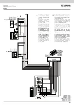
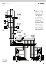
Disegno N° vc3040
Diagram N° vc3040
Dessin N° vc3040
Schaltplan NR. vc3040
Esquema N° vc3040
Esquema N° vc3040
Monitor
Moniteur
Art. / type
6000 + 6201 + 6145
Monitor
Moniteur
Art. / type 6306, 6326, 6506
Distributore
Distributor
Distributeur
Verteiler
Distribuidor
Distribuidor
Art. / type 6669
Ultimo Distributore
Last distributor
Dernier distributeur
Letzter Verteiler
Último distribuidor
Último Distribuidor
Art. / type 6669
Rete - Mains
Réseau - Netz
Red - Rede
Alimentatore
Power supply
Alimentation
Netzgerät
Alimentador
Alimentador
Art. 6568
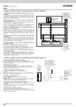
Togliere nella morsettiera del
monitor il ponte di collegamento
V3-M e settare il microinterruttore
posto sotto il monitor in posizione
doppino.
Remove the connection jumper
V3-M from the monitor terminal
block and set the microswitch
located under the monitor to the
twisted position.
Enlever dans le bornier
du moniteur le pontage de
raccordement V3-M et régler le
micro-interrupteur placé sous
le moniteur dans la position “ fil
téléphonique “ (2 fils).
Die Brücke V3-M der Monitor-
Klemmenleiste entfernen und
den Miktroschalter unter dem
Monitor auf „Schleife” stellen.
En la caja de conexiones del
monitor, quitar el puente de
conexión V3- M y configurar el
microinterruptor situado bajo el
monitor en posición par.
Retirar, na régua de bornes do
monitor, a ponte de ligação V3-M
e colocar o microinterruptor,
situado por baixo do monitor, na
posição par telefónico.
Monitor / Moniteur
Art. / type
6000 + 6201 + 6145
Monitor
Moniteur
Art. / type
6306, 6326,
6506
19
6568

