19
7602050
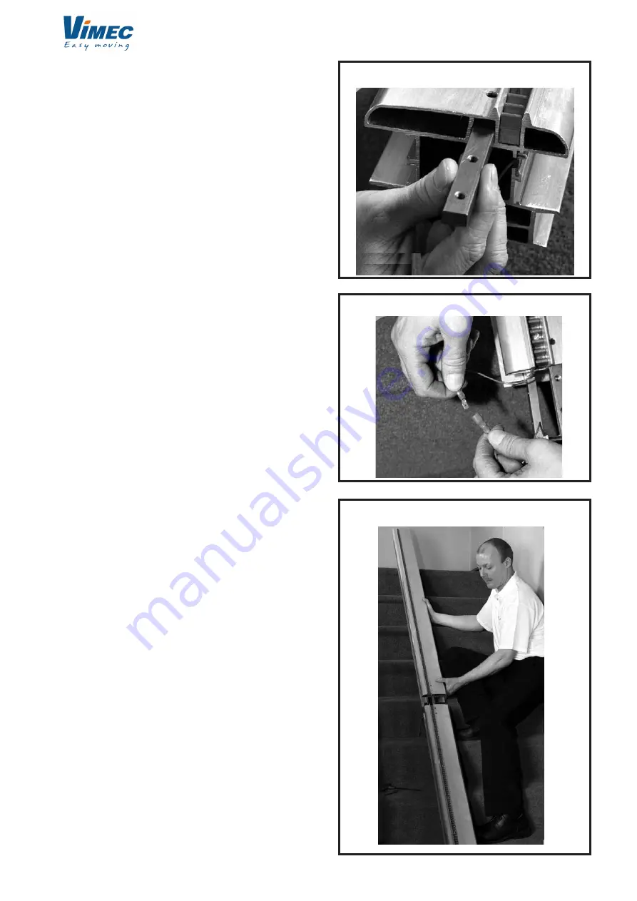
FIG.3
FIG.5
FIG.4
NOTE:
Ensure that the splice bars are positioned in
the track in the correct orientation. The splice bar has
three flat faces and one sloping face. The sloping face
MUST be positioned against the sloping face on the
extrusion as shown in (Fig. 3).
2.3-
Position the top section of track adjacent to
the bottom section of track (Fig. 4).
2.4-
For older machines: near the junction connect
the spade terminal connectors for the busbar charging
strip (Fig.5).
- For recent machines:
Kits now include a short copper strip that must be
placed across the track/busbar joint.
This replaces the copper adhesive tape and the
internal connection with the cables that were used
previously.
The installation instructions for this new connection
are explained below, and a copy is enclosed in each
installation kit.
1. Assemble the track as usual.
2. Slide the top of the load bar including the plastic for
approx. 100 mm.


