36
7602050
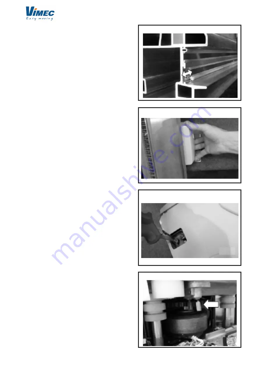
FIG.69
FIG.70
FIG.68
FIG.71
- If the track was not delivered pre-cut at the right
length, adjust the communication contact electrode to
the correct length for adapting the upper terminal cap
(Figure 68).
- Close the roller covers on the staircase support side
using the material supplied. Then, after placing the
track in the nearly correct position, put a screw in each
foot to stabilise the track (Figure 69).
- Attach the communication brush to the block,
remove the small cover from the left side of the block
(looking at the stairs), then remove the nut and the
ring terminal. Pass it through the brush supplied and
then replace the cable and the nut, lastly replace the
cover.
Note: Take care not to tighten the nut too much
(Figures 70 and 71).
- When the block is loaded, take care to correctly
position the two sensor load instruments of the contact
electrodes (Figure 72). The isolated load instrument
must be used on the communication brush (lower).
- To load the block, the DIP switch 2 on the main
printed circuit must be in the OFF position. Once the
block is loaded this switch must be in the ON position
to start the SlideTrack (see wiring diagrams).
Note: do not move the power supply block UP until
the upper terminal cap is correctly placed. The
connection electrode could move and damage the
carbon brushes.
- Connect the power supply to the main ring or fused
derivation. A “lazy” space 400 mm long must be left
along the staircase support, near the point under
the centre of the track where the power supply cable
enters the track. This allows the SlideTrack to travel
(Figure 73).
- Connect the upper group of track extremity safety
(terminal cap active) remembering to connect the
supplementary wires (Figures 74).
SlideTrack-Test
1. Using the remote control:
a. Bring the stairlift to the top of the staircase.
b. Press the DOWN button and keep it pressed.
c. Watch the stairlift in operation. It should:
i. move down the stairs at half speed, moving the
SlideTrack.


