7502116
CAUTION:
In the
B.R. - B.I. Version
, the platform
can only be operated with the down side bar in the
working position.
N.B.:
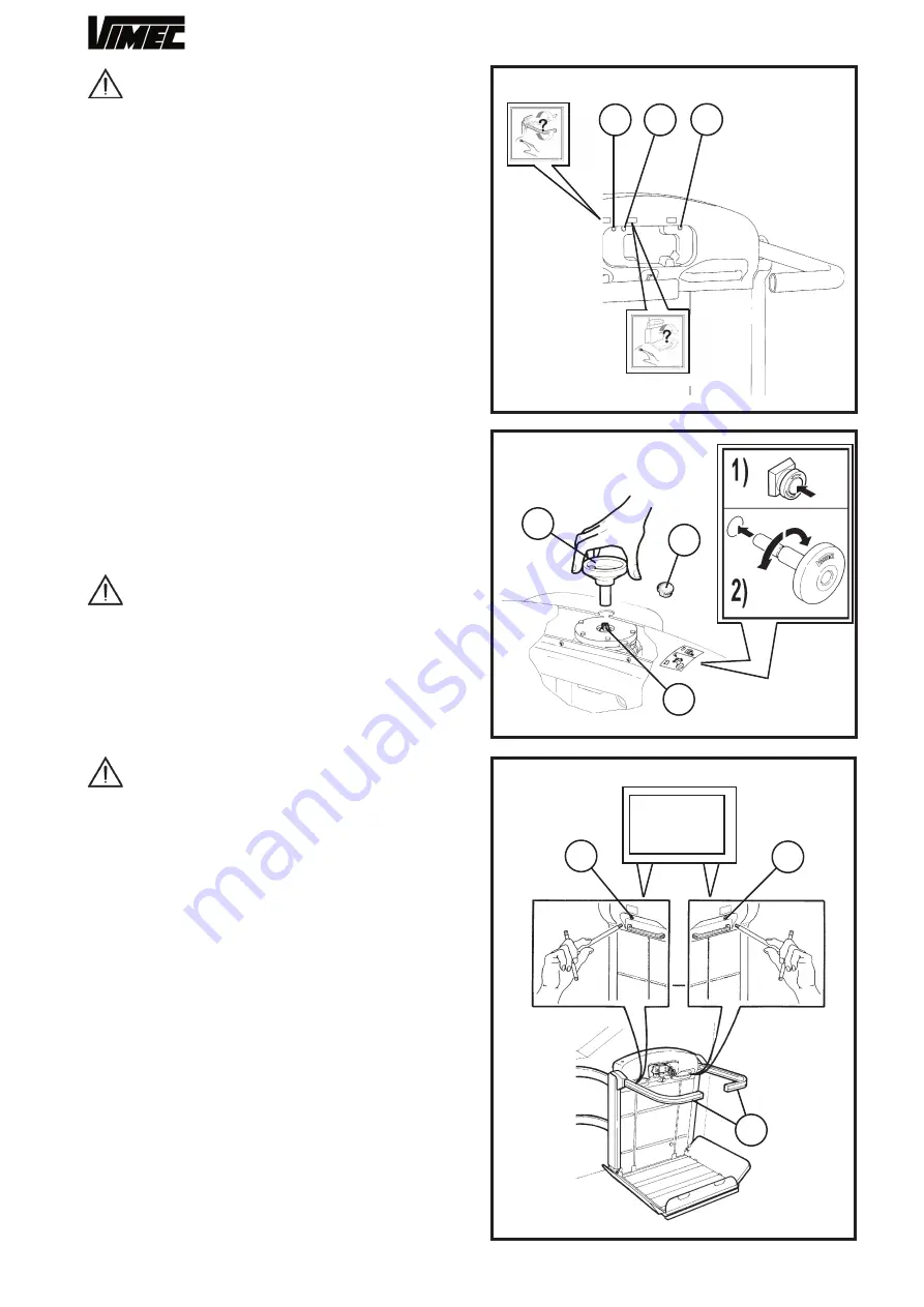
If the platform fold button is accidentally pressed
when someone is on the lift, a motor overload cut-out
is tripped, stopping the electromechanical actuator. Be-
fore using the lift, the cut-out must be reset by pressing
the button provided - Fig. 13/a.
7.3) Lift operated by attendant.
If the person who uses the system is not self-sufficient,
the lift may be operated by an attendant, using the same
control board - Fig. 2.
The guiding person must follow the machine subse-
quently from earth with respect to the moving direc-
tion.
7.4) Stairlift stopped at the other end of the stair-
case (optional call - send function).
1)
Insert the key in the control board at the floor and
turn it to ON - Fig. 9/a.
2)
Keep the call or send button (Fig. 9/c/d) pressed until
the lift has reached its destination.
3)
Remove the key from the control board, close the
rubber lid (Fig. 9/a).
CAUTION: Never send/call the lift to a floor
unless the WHOLE travel route can be seen.
7.5) Manual operation in emergency
Skill level OC: Trained operator with specific
skills
This emergency operating mode is used to bring the
person being transported to a floor in case of a power
black-out or a failure of the system.
CAUTION
: before operating in manual mode, the
operator
MUST
press the emergency switch
(STOP)
(Fig. 2/e) and remove the key.
After pressing the emergency switch, proceed as fol-
lows:
Moving the lift
1)
Remove the central cap from the casing (Fig. 14/a).
2)
Fit the handwheel provided (Fig. 14/b) into the hole,
fitting it into the square shaft (Fig. 14/c) and turn the
handwheel to move the lift.
3)
With the floor is reached, remove the handwheel
and replace the cap.
4)
Restore normal operation of the lift once the emer-
gency conditions cease.
Releasing the safety arms in an emergency
1)
Press the emergency STOP button.
2)
B.I. (Independent arms)
, unscrew the two arm
release screws on the front of the lift body above the
handle (Fig. 15/a)
2) B.R. (Retractable arms)
, screws at the bottom on
the front have to be undone (one for each safety arm
- Fig.16/a).
FIG.13
FIG.14
FIG.15
BARS
RELEASE
EMERGENCY
11
b
a
a
b
c
b
a
b
a
Summary of Contents for V64-74 B.I.
Page 37: ...37 7801228 BARRE DI SICUREZZA...
Page 40: ...40 7801229 BARRE DI SICUREZZA RETRATTILI...
Page 43: ...43 7801230 PROTEZIONI SOLO PER MOD V64 SOLO PER MOD V74...
Page 45: ...45 6 9 8 7 10 4 2 1 7 7 1 2 11 13 12 1 2 5 3 7801231 GUIDA...
Page 47: ...47 3 7801232 1 4 5 6 7 8 8 2 14 12 9 10 11 13 6 PANNELLO ELETTRICO B I...
Page 51: ...51 7804457 1 2 3 4 CAVI AZIONAMENTO PEDANA BANDELLA BARRE INDIPENDENTI BARRE RETRATTILI...


