7502116
3)
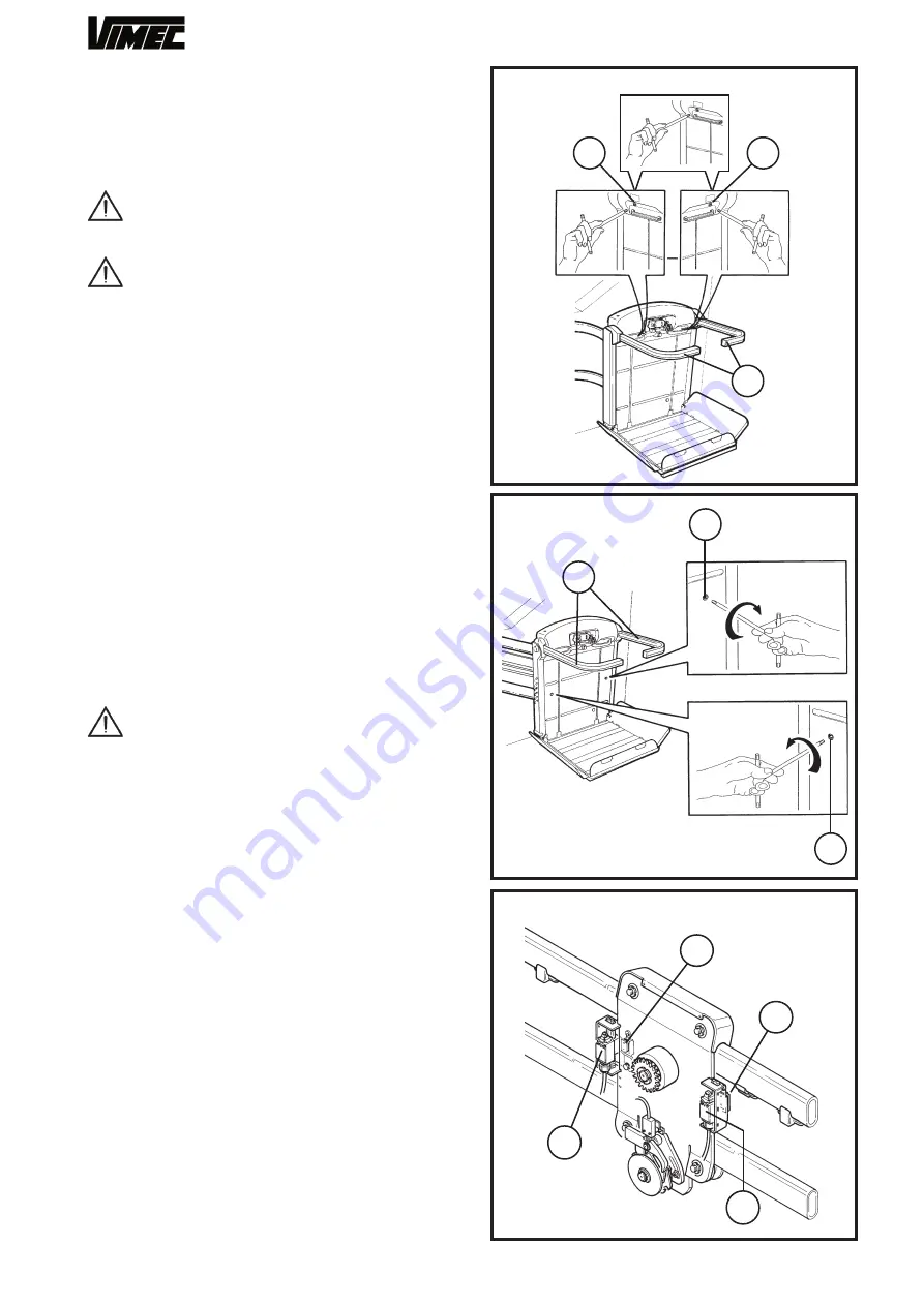
Raise the arms by hand (Fig.15/b-16/b) and hold
them in position while the passenger gets off the lift.
4)
Screw the release screws down again, holding the
arm in the working (lowered) position (Fig. 15b).
5)
Check that the arms are fixed.
6)
Reset the emergency STOP button.
CAUTION
:
During the emergency operations
do not forget that the safety arms are not fixed in
the opening position.
CAUTION: In case of a system failure or trip-
ping of the safety gear, call in an authorised VIMEC
technician. In case of any kind of malfunction, put
the lift out of use by turning the master switch to
OFF.
8) SAFETY SYSTEMS
8.1) Devices to prevent impacts and shearing along
the travel rails.
When in motion, the platform and the body of the lift
are protected by sensor guards which stop the lift if it
touches an obstacle of any kind - Fig. 5.
However, they do allow the lift to be moved in the
opposite direction to that in which the obstacle was
encountered, to allow removal of the obstruction.
8.2) Safety devices for the user.
a) Safety gear
- Fig. 6/a.
The stairlift is equipped with a gradual action mechani-
cal safety gear.
It is tripped if the drive components fail, or if the nor-
mal downward travel speed is exceeded by a pre-set
amount. When tripped, this device stops the lift.
CAUTION: in this case the lift remains locked
out of use and an authorised VIMEC technician
must be called in to put it back into service.
b) Bars and guard boards
During use the platform (Fig. 11/d) is protected by
two bars (Fig. 11/a) about 100 cm above the platform
surface. The platform is also protected by two guard
boards (Fig. 11/b) which have the dual function of facili-
tating access to the stairlift at the floors (open position)
and of retaining the wheelchair while the lift is moving
(safety position at 50°, approximately 125 cm beyond
the platform surface).
Before the stairlift leaves the floor, the bars and guards
automatically move to the safety position.
The guard facing in the downward direction only opens
at the lower floor.
If the bars or guards encounter an obstacle as they
move into position, an overload cut-out is tripped, pre-
venting operation of the lift. To restore normal opera-
tion, press the overload cut-out reset buttons on the lift
control panel (Fig. 13).
c) Handles
In the top of the lift body, they can be used as rests
while the lift is in motion - Fig. 11/c.
FIG.17
FIG.16
FIG.18
12
a
a
b
b
a
a
b
a
a
b
Summary of Contents for V64-74 B.I.
Page 37: ...37 7801228 BARRE DI SICUREZZA...
Page 40: ...40 7801229 BARRE DI SICUREZZA RETRATTILI...
Page 43: ...43 7801230 PROTEZIONI SOLO PER MOD V64 SOLO PER MOD V74...
Page 45: ...45 6 9 8 7 10 4 2 1 7 7 1 2 11 13 12 1 2 5 3 7801231 GUIDA...
Page 47: ...47 3 7801232 1 4 5 6 7 8 8 2 14 12 9 10 11 13 6 PANNELLO ELETTRICO B I...
Page 51: ...51 7804457 1 2 3 4 CAVI AZIONAMENTO PEDANA BANDELLA BARRE INDIPENDENTI BARRE RETRATTILI...


