7602116
f)
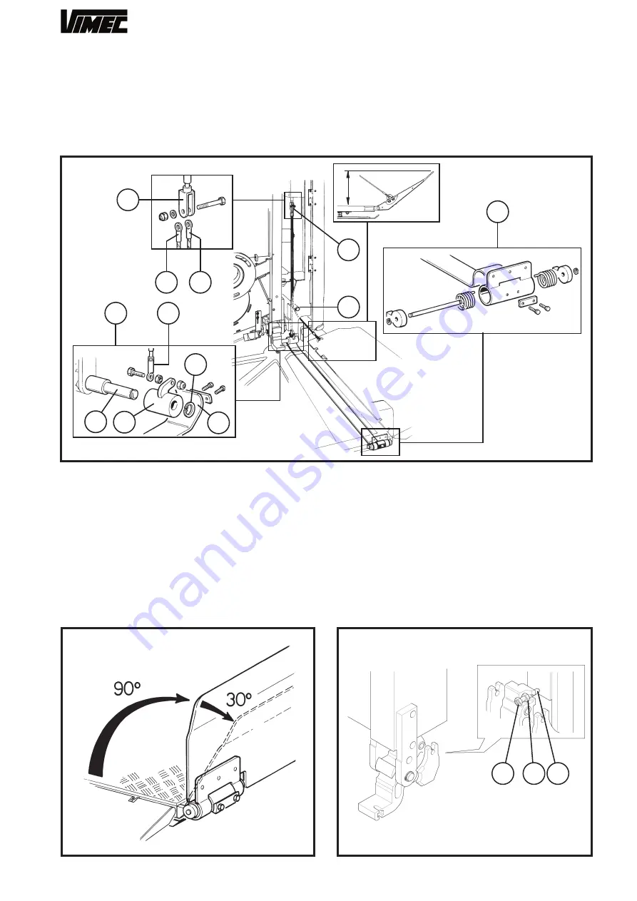
Connect the lateral guard board operating cables (Fig.
24/f) and frontal (Fig. 24/e) to the fork (Fig. 24/b).
- Tighten with nut and screw.
- Insert the eccentric (Fig. 24/h) with handling belt (Fig.
24/g), front chute on the special pin (Fig. 24/i) and
block with seeger (Fig. 24/m).
FIG.24
B.R.:
fix the cable (Fig. 24/f) already present on the
side bar chute with special screws.
- Fix the cable eye (Fig. 24/e) to the eccentric (Fig.
24/h) by screw, nut and lock nut leaving the necessary
clearance for the rotation of the eye itself.
Proceeds to check the proper working of the front ac-
cess chute:
- Check the angle between the chute (in working posi-
tion) and the footboard is 90° (Fig. 25).
- Check the front access micro chute intervenes with a
maximum rotation of 30° of the same chute with respect
to the working position as in Fig. 25.
- If the guards are not opened or closed correctly,
adjust to the specified position using the register fork
(Fig.21/b).
FIG.25
FIG.26
g)
Replace the top plate on the platform using the
relative fixing screws.
h)
Remove the wedge and the plastic clamp (Fig.
21/c/d) used to keep the platform horizontal during the
adjustments from the platform supports.
i)
Tighten with a driving torque of 4 daN ± 0,1the dowel,
the nut and the locknut (Fig. 26/a,b,c).
l)
Check friction group is engaged.
22
125
b
a
d
f
e
b
b
c
h
i
m
g
c
e
a
Summary of Contents for V64-74 B.I.
Page 37: ...37 7801228 BARRE DI SICUREZZA...
Page 40: ...40 7801229 BARRE DI SICUREZZA RETRATTILI...
Page 43: ...43 7801230 PROTEZIONI SOLO PER MOD V64 SOLO PER MOD V74...
Page 45: ...45 6 9 8 7 10 4 2 1 7 7 1 2 11 13 12 1 2 5 3 7801231 GUIDA...
Page 47: ...47 3 7801232 1 4 5 6 7 8 8 2 14 12 9 10 11 13 6 PANNELLO ELETTRICO B I...
Page 51: ...51 7804457 1 2 3 4 CAVI AZIONAMENTO PEDANA BANDELLA BARRE INDIPENDENTI BARRE RETRATTILI...


