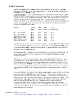
8.
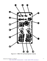
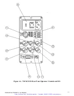
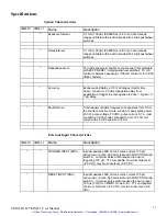
115 VAC 60Hz. /230 VAC 50Hz.
Input module. Mates with female IEC plug on supplied line cord.
Includes the following additional functions:
a. Power switch – “0” is off, “1” is on.
b. Power fuses: ½Amp SB for 115 VAC 60Hz., ¼Amp SB for 230 VAC 50Hz. See “Line Fuse
Replacement” instructions.
c. Voltage change switchover block. See “Voltage Change” instructions.
d. 3A line filter. (Internal, not user accessible)
9.
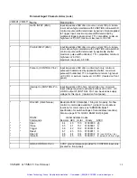
AUX/GND/+5V
accessory block. 3-pin pluggable terminal block connector. +5V and ground is
available in addition to an AUX signal. The controller type determines the AUX signal function. The
VMM-T1
AUX output is now the DELAY timer output signal. An active high pulse is presented to
this output equal to the length of the DELAY timer setting. See “DELAY Out (AUX pin 1)” under
EXTERNAL OUTPUT CHARACTERISTICS. The
VMM-D1
AUX output is an active low pulse
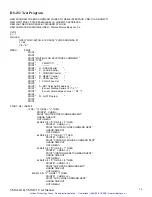
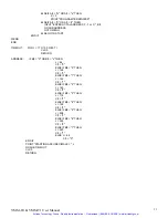
output that can be toggled TTL high and low from commands presented to the RS-232C control input.
See “RS-232 Out (AUX pin 1)” under EXTERNAL OUTPUT CHARACTERISTICS.
10.
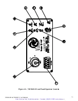
FUNCTION
switches. Five sub-miniature slide switches.
A-D
switches are used to select the active
states of each of the four input BNC input connectors. (See “FUNCTION select” under GENERAL
CHARACTERISTICS.) The
E
switch is used to select the proper pulse energy for the shutter being
driven. Switch to the HIGH (up) position for the VS35 (35mm aperture) and the VS45 (45mm aperture)
types, switch to the LOW (down) position for all other shutter types.
11.
SYNC. OUTPUT
BNC. Active low output for shutters equipped with the SOLID STATE
SYNCHRONIZATION SYSTEM option. The shutter’s internal sync. circuit sets the BNC to a low
level when the sync. circuit becomes active. The output goes low when the shutter reaches 80% of full
open, and goes to the high state when the shutter reaches 20% closed. The front panel SYNC. ACTIVE
LED illuminates when the sync. is active.
12.
PULSE OUTPUT
BNC. Active low output. The duration of this pulse is equal to the duration of the
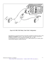
shutter exposure pulse. This output can be used to daisy chain
VMM-D1
/
T1
units together. A TTL
exposure pulse input to the PULSE INPUT BNC will appear at the PULSE OUTPUT BNC. The pulse
width output is equal to the duration set on the EXPOSURE timer (
VMM-T1
only).
Note toggling the
N.O./N.C. will
not
change the state of the PULSE OUTPUT.
VMM-D1 & VMM-T1 User Manual
24
Artisan Technology Group - Quality Instrumentation ... Guaranteed | (888) 88-SOURCE | www.artisantg.com

