TABLE OF CONTENTS
WARRANTY .................................................................................................................................................................. 3
GENERAL SAFETY SUMMARY ................................................................................................................................ 6
Injury Precautions .......................................................................................................................................... 6
Product Damage Precautions ......................................................................................................................... 6
Safety Terms and Symbols ............................................................................................................................. 7
PREFACE ....................................................................................................................................................................... 8
GETTING STARTED .................................................................................................................................................... 9
Features............................................................................................................................................................ 9
Introduction................................................................................................................................................... 10
Start Up.......................................................................................................................................................... 11
Line Fuse Replacement................................................................................................................................. 11
Voltage Change ............................................................................................................................................. 12
Figure #1 - AC Input Module....................................................................................................................... 12
Initial Operation and Testing....................................................................................................................... 13
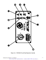
VMM-D1 FRONT PANEL OPERATOR CONTROLS ........................................................................................... 15
Figure #2 – VMM-D1 Front Panel Operator Controls ............................................................................. 14
Description..................................................................................................................................................... 15
Notes............................................................................................................................................................... 17
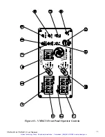
VMM-T1 FRONT PANEL OPERATOR CONTROLS ........................................................................................... 19
Figure #3 – VMM-T1 Front Panel Operator Controls.............................................................................. 18
Description..................................................................................................................................................... 19
Notes............................................................................................................................................................... 21
VMM-T1/D1 REAR PANEL OPERATOR CONTROLS......................................................................................... 23
Figure #4 – VMM-T1 /D1 Rear Panel Operator Controls and I/O........................................................... 22
Description..................................................................................................................................................... 23
OPERATING BASICS................................................................................................................................................. 25
Function Switches ......................................................................................................................................... 25
GATE INPUT................................................................................................................................................ 25
Figure #5 GATE Input Timing Diagram .................................................................................................... 26
Mode Selection............................................................................................................................................... 28
RS-232C Operation...................................................................................................................................... 28
Figure #6 VMM-T1 /D1 Daisy Chain Cable Configuration....................................................................... 29
RS-232 Test Program.................................................................................................................................... 30
Shutter Frequency of Operation ................................................................................................................. 32
Trigger Cautions and Trouble Shooting Tips ............................................................................................. 32
Pulse Voltage Graphs.................................................................................................................................... 33
Figure #7 Pulse Voltage vs. Exposure Time ................................................................................................ 33
Figure #8 Pulse Voltage vs. Frequency........................................................................................................ 33
Figure #9 Overall VMM-D1 Dimensions..................................................................................................... 34
Figure #10 Overall VMM-T1 Dimensions................................................................................................... 36
Maintenance .................................................................................................................................................. 37
SPECIFICATIONS....................................................................................................................................................... 37
System Characteristics.................................................................................................................................. 37
External Input Characteristics..................................................................................................................... 37
External Output Characteristics.................................................................................................................. 39
General Characteristics ................................................................................................................................ 40
INDEX ........................................................................................................................................................................... 43
VMM-D1 & VMM-T1 User Manual
5
Artisan Technology Group - Quality Instrumentation ... Guaranteed | (888) 88-SOURCE | www.artisantg.com


