41
CONNECTIONS FOR THE STANDBY CONTROL
(POWER CONTROL)
Many AV-Systems consist of a multitude of individual components. To avoid the necessity of switching
them on and off before and after every use, many manufacturers have equipped their devices with what
is known as “POWER CONTROL” circuit or “TRIGGER”. This kind of remote-controlled standby circuit is
used primarily for preamplifier and power amplifiers. To employ these functions, direct or indirect cable
connections must be made between the preamplifier (or integrated amplifier) and all the devices which
support this function. The “POWER CONTROL” function operates in such a way that each switching on
or off of one device in the system (usually the preamplifier) automatically brings about the switching on
or off of all the connected devices which support this function. Please keep in mind that all devices which
respond to the power control are not disconnected from the mains network when switched off. They are
set to a standby state instead. For connecting cables, two-core cables with 3.5 mm jack plugs (mono)
are used. For each connection between two devices one of those cables is needed.
If you don‘t wish to use this function or if the other components do not support it, all you have to do is
leave out these cable connections.
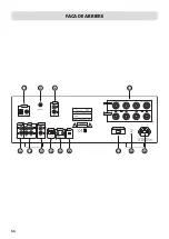
The SV-228 is equipped with two output connectors for the power control. Here, the switching signal
generated by the SV-228 is available for other components of the system. Two HiFi components that are
able to react to the power control signal can be connected directly to the amplifier‘s power control out-
puts (19). If more than two devices, which can be controlled, are to be connected, then it is necessary to
make the power control connection between the amplifier and these further devices through the outputs
of the two devices which are connected directly. For that reason, every HiFi component that accepts po-
wer control signals is also equipped with a power control output. Thus, in theory it is possible to provide
an infinite number of HiFi components with the power control signal. This approach, to loop a signal
through a chain of components, is commonly referred to as “daisy chaining”.
Many devices which can be controlled by a switching signal (not preamplifiers or
integrated amplifiers), have two terminals which do not differentiate between input and
output. In this case either of the two can be selected.
“POWER CONTROL” sockets of preamplifiers or integrated amplifiers must not be inter-
connec-ted! All receiving devices must not be connected to more than one preamplifier or
integrated amplifier (directly or indirectly)!
e.g. Main amplifier

