15
www.vintageair.com
900194 REV B 09/16/19, PG 15 OF 42
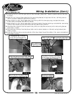
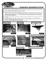
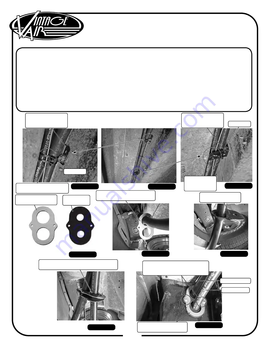
Route the A/C hoses into the channel on the inner fender, and install the (2) A/C hose fenderwell brackets
onto the OEM bolts using (2) 5/16” nuts (See Photos 5, 6 & 7 below).
Secure the A/C hoses to the A/C hose fenderwell brackets using the supplied tie wraps (See Photos 5 & 7,
below).
Locate the firewall cover plate and rubber boot (See Photo 8, below).
Route the 90° hose fitting of the #10 A/C hose through the firewall cover plate (See Photo 9, below).
Install the rubber boot onto the #10 A/C hose (See Photo 10, below).
Route the #6 A/C hose through the firewall cover plate and rubber boot (See Photo 11, below).
Install the rubber boot and the firewall cover plate using (2) #10 x 1/2” sheet metal screws into the
previously drilled 5/32” holes in the inner fender kick panel grommet location (See Photo 12, below).
Route the #6 and #10 A/C hoses through the kick panel opening in the passenger compartment.
A/C Hose Routing & Kick Panel
Cap Installation (Cont.)
5.
6.
7.
8.
9.
10.
11.
12.
Route #10 90° Hose Fitting
Through Firewall Cover Plate
Photo 9
Photo 8
Photo 10
Photo 11
Photo 12
Install Rubber Boot and Firewall
Cover Plate with (2) #10 x 1/2”
Sheet Metal Screws
Route #6 A/C Hose Through A/C Hose
Fenderwell Bracket and Rubber Boot
Install Rubber Boot
onto #10 A/C Hose
Firewall Cover Plate
646954
Rubber Boot
338611
Photo 7
#10 A/C Hose
#6 A/C Hose
Inner Fender Kick Panel
Grommet Location
A/C Hose
Fenderwell Bracket
646967
A/C Hose
Fenderwell Bracket
646967
Photo 6
Photo 5
5/16” Nut
Secure Hoses to
Brackets with Tie Wraps
Secure Hoses
to Brackets
with Tie Wraps
5/16” Nut


