17
www.vintageair.com
900194 REV B 09/16/19, PG 17 OF 42
A/C Hose Routing & Kick Panel
Cap Installation (Final)
19.
20.
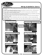
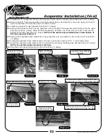
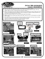
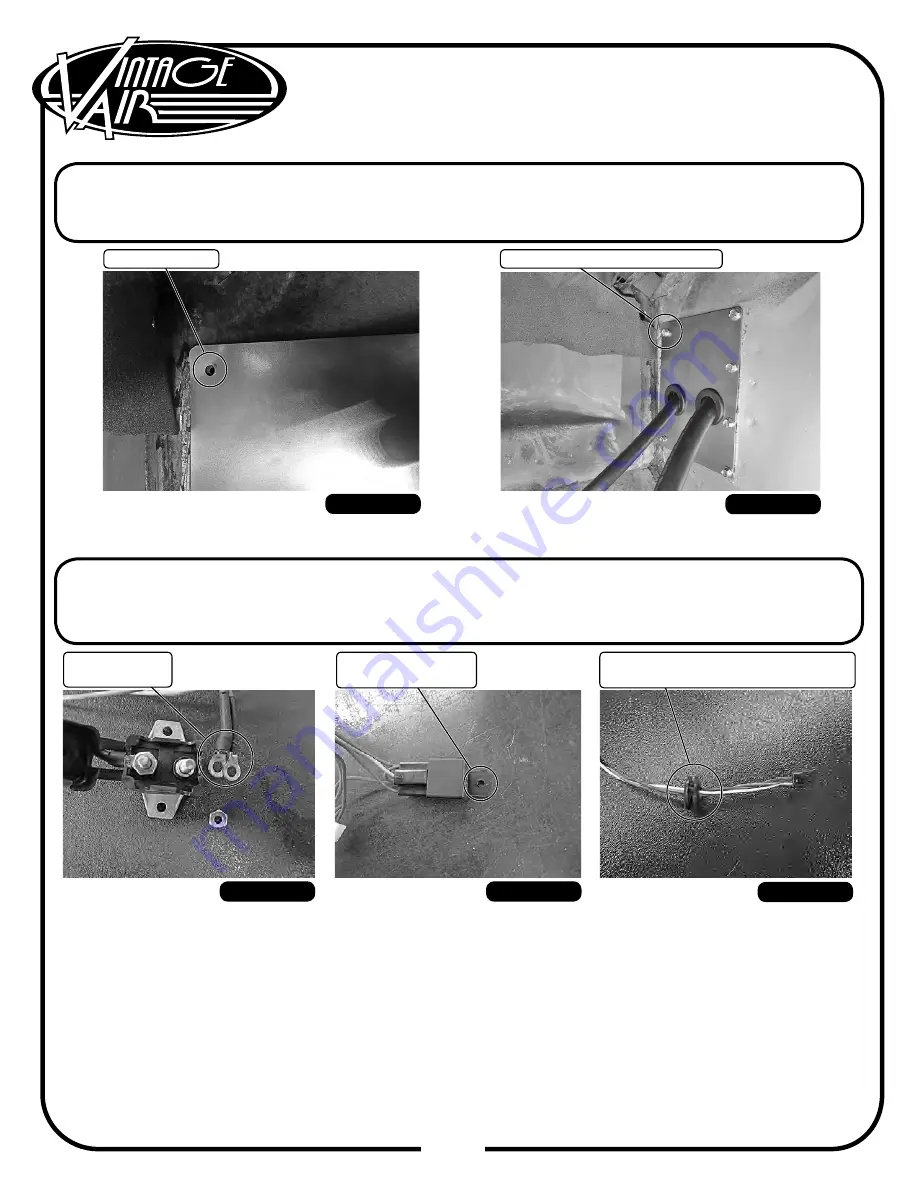
Using the kick panel caps upper left hole as a template, drill a 3/16” hole into the kick panel (See Photo 18,
below). NOTE: Some vehicles may have this hole predrilled.
Install a #14 x 3/4” sheet metal screw into the upper left hole of the kick panel cap into the kick panel (See
Photo 19, below).
Photo 18
Drill 3/16” Hole
#14 x 3/4” Sheet Metal Screw
Photo 19
Wiring Installation
1.
2.
3.
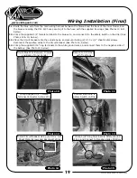
Disconnect the circuit breaker from the main wiring harness (See Photo 1, below).
Enlarge the hole on the relay mounting tab to accommodate the #14 x 3/4” sheet metal screw installed on
the kick panel cap (See Photo 2, below).
Route the heater control valve plug through the 3/8” ID x 7/8” OD grommet (See Photo 3, below).
Disconnect
Circuit Breaker
Photo 1
Photo 2
Photo 3
Enlarge Hole on
Relay Mounting Tab
Route Heater Control Valve Plug
Though 3/8” ID x 7/8” OD Grommet


