35
www.vintageair.com
900194 REV B 09/16/19, PG 35 OF 42
Wiring Final Steps
1.
2.
3.
4.
5.
6.
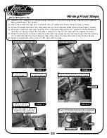
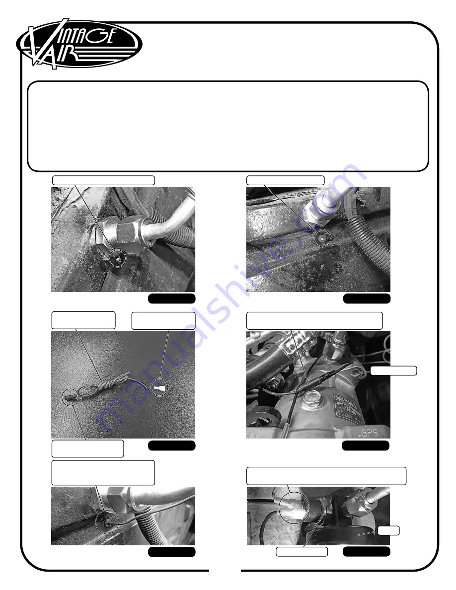
Install the 1/4” grommet into the previously drilled 9/32” hole on the inner fender under the #10 bulkhead
fitting (See Photos 1 & 2, below).
Locate the compressor lead wire, and cut off the 1/4” female terminal as shown in Photo 3, below.
Connect the bullet terminal of the compressor lead to the compressor bullet terminal (See Photo 4, below).
Route the compressor lead wire along the #10 A/C hose and through the 1/4” grommet into the fenderwell
(See Photo 5, below). Secure the compressor lead wire to the #10 A/C hose with the supplied tie wraps.
Under the fenderwell, continue routing the compressor lead along the #10 A/C hose toward the drier. Crimp a
1/4” female terminal onto the compressor lead, and connect it to the safety switch (See Photo 6, below).
Secure the compressor lead to the #10 A/C hose with tie wraps.
Photo 6
Crimp 1/4” Female Terminal onto Compressor
Lead and Connect to Safety Switch
Photo 5
Route Compressor Lead Wire
Along #10 A/C Hose and
Through 1/4” Grommet
Photo 4
Connect Bullet Terminal of Compressor
Lead to Compressor Bullet Terminal
Photo 3
Compressor Lead
23135-VUW
Cut Off 1/4”
Female Terminal
Bullet Connection
of Compressor Lead
Photo 1
Previously Drilled 9/32” Hole
Photo 2
Install 1/4” Grommet
Compressor
Safety Switch
Drier

