background image

User Manual   

Espace Walk-in Cellar

14

Installing your cellar (cont'd)

WARNING: Each of the pre-drilled bolt holes in the wall 

panel have a captive nut secured inside them, which will 

receive the


bolts that attach the conditioner unit. 

DO NOT use an impact drill or a drill with a high clutch/

torque setting to drive in the bolts – this will break the 

adhesive that holds the nut in place and dislodge it, 

making it impossible to secure the bolts. Insertion of 

the bolts should be started by hand to ensure they are 

aligned correctly and not cross-threaded, and then can 

be carefully completed using either a manual socket 

wrench or a drill on a low clutch/torque setting.

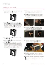
23 Do the same for the bottom metal bracket (note that the 

brackets face in opposite directions).

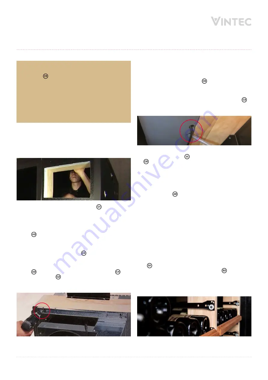
24 Temporarily position the timber frame between the two 

brackets, ensuring that its inner edges align with the 

edges of the wall panel cutout (see below).

25 Using a pencil, mark the position of the 


metal brackets’ 

screw holes on the top and bottom of the timber frame.

26 Remove the timber frame from the wall panel, as well as 

carefully removing the bolts and brackets. 

27 Use   screws to securely attach the top metal bracket 

onto the timber frame using your pencil marks as a 

position guide. Do the same for the bottom metal bracket.

28 Insert the main conditioner unit   through the timber 

frame (ensuring that the foam shock absorber strip is on 

the lower side), and rest the conditioner onto the foam strip.

29 Use   screws to securely attach the conditioner   to 

the timber frame 


by screwing from the rear side of  

the conditioner through its metal edge flange and into  

the timber frame (see below).

30 Prepare the condensation water hose connection on 

the base of the conditioner unit by removing the plastic 

shroud over the hose connector outlet. 

31  Connect the condensation hose   by sliding it onto the 

connector outlet, and secure it using the spring clamp.

32 Feed the ends of the condensation hose and the power 

cable through their outlet holes in the rear grill cover 


(see below) and re-attach the grill cover to the body of  

the conditioner unit.

33 Lift the conditioner/frame assembly into position and 

attach it to wall panel 

 by carefully re-inserting the two  

 bolts (including the wide washers this time) through 

the metal brackets 

(see warning after step 22 above)

34 Feed the power lead out through the pre-cut hole in the 

roof panel, ready for connection to mains power.

35 Standing inside the cellar, take one half of the plastic hole 

cover grommet


and ease it sideways onto the power 

lead via the grommet’s pre-cut slit so that the power lead 

runs up through the centre of the grommet, then slide the 

grommet up to the ceiling and press it into the roof hole 

so that it forms a tight seal.

36 From outside the cellar, use a step ladder to access the 

roof and repeat step 

35 by attaching the other half of the 

grommet to the power lead, then slide it down and press  

it firmly into the roof hole to seal it.

Interior shelving assembly

37 Sort and arrange the various vertical timber shelving 

support frames. Those with shelf runners only on one side 

– 

 – should be installed at the front and back of the 

cellar. Those with runners on both sides – 

 – should be 

installed in the centre. Take care to ensure the supports 

are facing in the correct direction (front to back, and top 

to bottom) so that shelves can slide onto their runners 

correctly (see below for reference).

Summary of Contents for ESPACE Series

Page 1: ...User Manual ESPACE1000 KIT ESPACE1500 KIT ESPACE2000 KIT ESPACE2500 KIT ESPACE3000 KIT ESPACE3500 KIT ESPACE4000 KIT ESPACE1000 EXT Espace Walk in Cellar vintec com...

Page 2: ...persons including children with reduced physical sensory or mental capabilities or lack of experience and knowledge unless they have been given supervision or instruction concerning use of the applian...

Page 3: ...eet white Bordeaux 6 Dry white Bordeaux 8 Bordeaux reds 17 Burgundy whites 11 Burgundy reds 14 Champagne 6 Jura 10 Languedoc Roussillon 13 Provence Ros 12 Savoie 9 Dry white Loire wines 13 Sweet white...

Page 4: ...re display Compressor operation indicator Abnormal temperature alarm Defrost cycle operation indicator Heater operation indicator Decrease temperature Set mute Standby increase temperature Exhaust air...

Page 5: ...packaging to a refuse collection point For the most part it will be recycled Recycling a caring gesture Electrical and electronic equipment can have a harmful effect on the environment and human healt...

Page 6: ...286 514 238 150 462 381 374 524 320 FRONT VIEW INTERIOR VIEW SIDE VIEW SIDE VIEW TOP VIEW NOTE Illustrations not to scale All dimensions in millimetres Cellar dimensions Conditioner dimensions 1170 18...

Page 7: ...ven to site accessibility as well as the safe lifting capacity of any equipment being used to transport and manoeuvre the crates ASSEMBLY The cellar should be assembled in the same room or space as it...

Page 8: ...rlocking design of the wall panels the conditioning unit can only be installed next to the door on the front right side of the cellar when viewed from outside Excess humidity moisture removal The cond...

Page 9: ...User Manual Espace Walk in Cellar 8 Installing your cellar cont d Components list CELLAR COMPONENTS...

Page 10: ...User Manual Espace Walk in Cellar 9 Installing your cellar cont d ASSEMBLY COMPONENTS A1 A3 A4 A6 A5 A7 A8 A2...

Page 11: ...User Manual Espace Walk in Cellar 10 Installing your cellar cont d CONDITIONER COMPONENTS SHELVING COMPONENTS Exterior Door frame Interior C1 S1 C2 S2 C3 C4 S3 S4 S5 S6 C5 C6...

Page 12: ...ladder to enable access to the cellar s roof once assembled Unscrew whichever of the door hinges will become the upper hinge see warning note after step 10 and dismount the door which will be replaced...

Page 13: ...secure panels and with adhesive tape see below 9 Position right side panel nested against to form the rear right corner of the cellar and secure the corner with adhesive tape see below 10 Slot front...

Page 14: ...adjust the sides and apply pressure to the roof to ensure it is pressed down firmly see below 17 Ensure that all other panels are also firmly pressed together tightly so that no space is left between...

Page 15: ...ge flange and into the timber frame see below 30 Prepare the condensation water hose connection on the base of the conditioner unit by removing the plastic shroud over the hose connector outlet 31 Con...

Page 16: ...e central double sided support frame and screw it to the drilled cross bars to secure it then go back and firmly secure the screws attached at step 40 42 Repeat steps 40 and 41 to attach drilled cross...

Page 17: ...se a glass to yourself Adding extension modules ESPACE1000 EXT The Espace range enables you to expand your wine collection by adding extension modules that increase the capacity of the standard cellar...

Page 18: ...level at 1m at 3m N A N A 46dB 40dB Airflow inside cellar N A N A 96m3 h at 198m3 h Airflow outside cellar N A N A 179m3 h 1 Based on a 750mL Standard Bordeaux Bottle 2 In a well isolated cellar Maint...

Page 19: ...lves If you need to stack bottles for long term cellaring it is best to use the shelf lock for safety and avoid sliding out those stacked shelves The lock is located at the back left corner of each st...

Page 20: ...e Indicates that an automatic defrosting cycle is underway D Heater Indicates that the heater is operating NOTE When there has been a significant modification in set temperatures it can take several h...

Page 21: ...User Manual Espace Walk in Cellar 20 Notes...

Page 22: ...User Manual Espace Walk in Cellar 21 Notes...

Page 23: ...including failure to properly maintain or service iii improper negligent or faulty servicing or repair works done by anyone other than an Electrolux authorised repairer or ASC iv normal wear and tear...

Page 24: ...ce by following us vintecclub Vintec We are part of the Electrolux Family To add a touch of professional inspiration to your home visit electrolux com au Service and support 1800 771 776 concierge vin...

Reviews: