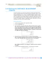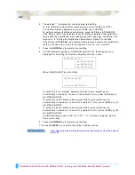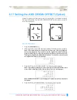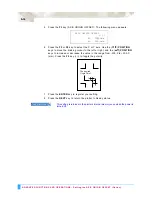
ADVANCED FUNCTIONS AND OPERATIONS : Setting the SENSOR OFFSET ADJUSTMENT (Method 1)
6-40
7
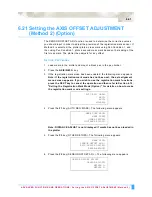
Press the
F3
key (METHOD 1). The following menu appears.
8
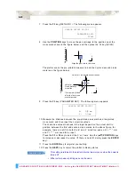
Use the
POSITION
keys to move the pen carriage to the position near the
cross mark shown in the figure below, and then press the F4 key (SCAN).
The plotter scans the pre-printed cross mark, and then plots a second cross
mark (see the figure below).
9
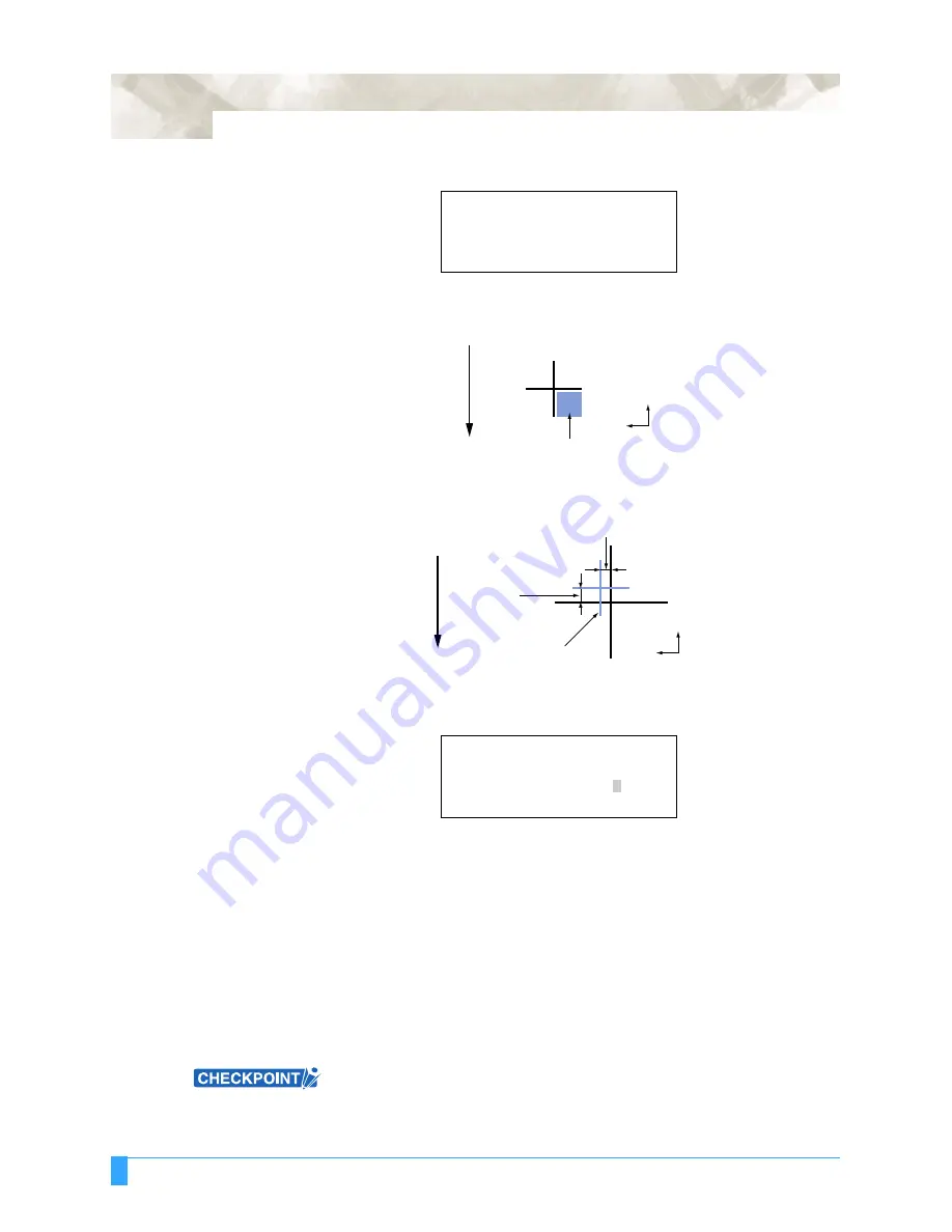
Press the
F3
key (PARAMETER SET). The following menu appears.
10 Measure the distance between the pre-printed cross mark and the plotted
cross mark, and then input the corrective values.
The corrective values that need to be input depend on the actual shift in
position between the first and second cross marks. In the above figure, for
example, there is a shift in both the -X and -Y direction, and so X = -**.* mm
and Y = **.* mm need to be input.
Press the
F3
or
F4
key to select the X or Y axis. Use the (
▲▼
)
POSITION
keys
to increase or decrease the value. (If there is no shift, simply press the
ENTER
key).
11 Press the
ENTER
key to register your setting.
12 Press the
NEXT
key to return the plotter to Ready status.
This setting is retained in the plotter’s internal memory even when the power is
turned off.
•
Either cutter peas or plotting pens can be used.
SENSOR OFFSET ADJUST
PARAMETER SET>
SCAN>
SENSOR OFFSET ADJUST
X=
0.
mm
X=
0.0 mm
X
Y
Media feed direction
Align the pen’s tip in this area
Value for
X-axis distance
correction
Value for Y-axis distance correction
X
Y
Media feed direction
Cross mark plotted
after the first cross
mark was read
0
Summary of Contents for Q100
Page 34: ...Cutter Blades and Cutter Pens Adjusting the Blade Length 2 6 ...
Page 64: ...Pen Setting Conditions Adjusting the Blade Length 4 12 ...
Page 140: ...ADVANCED FUNCTIONS AND OPERATIONS Selecting the Type of Perforated Line 6 62 ...
Page 148: ...OPTIONS Pen Offset for 2 pen models only 7 8 ...
Page 174: ...INTERFACES COMMAND Settings 10 8 ...


